If it's a depletion mode fet, then depending on the matching and
relative Vds figures the Gate may be negative with respect to the output.
😎
relative Vds figures the Gate may be negative with respect to the output.
😎
If it's a depletion mode fet, then depending on the matching and
relative Vds figures the Gate may be negative with respect to the output.
😎
Hi Mr Pass,
Stupid question from me again.
1) How many VA for T1 and what is the suitable VDS if i use "IXTH6N50D2"?
2) is the sound better than the bulb ?
😀
Thanks
Great ! Infact in this case , not matching the D Fets , the gate to output voltages are -2 and -4 V.If it's a depletion mode fet, then depending on the matching and
relative Vds figures the Gate may be negative with respect to the output.
😎
My experience is that you can use an IRFP240 as the upper
transistor and save lots of money. To the extent that you
want a pure current source and can spare a volt, you can
raise the value of its Source resistor also.
😎
transistor and save lots of money. To the extent that you
want a pure current source and can spare a volt, you can
raise the value of its Source resistor also.
😎
My experience is that you can use an IRFP240 as the upper
transistor and save lots of money. To the extent that you
want a pure current source and can spare a volt, you can
raise the value of its Source resistor also.
😎
And it works 😀. Thanks a lot . So I set R5 1,47 for now , if it is correct probably we can also rise the rail Voltage to 40 volts or so 🙂
Attachments
You are fast Stefano!
IRFP240 must drop at least 4 volts. What is your drain voltage and current draw now?
This is turning out to be a great little 'tutorial' amp.
IRFP240 must drop at least 4 volts. What is your drain voltage and current draw now?
This is turning out to be a great little 'tutorial' amp.
You are fast Stefano!
IRFP240 must drop at least 4 volts. What is your drain voltage and current draw now?
This is turning out to be a great little 'tutorial' amp.
The current is the same , as set from the self-biasing D mosfet Q1 and is 1,6 A . Drain voltage at half the rail like before .
Great to have a definitive (for the moment) diagram.
Thank you Stefano (and goes without saying: thank you Papa too)
Thank you Stefano (and goes without saying: thank you Papa too)
I may have missed it, but what sonic difference does it make?
Fran
Any ideal what is the output wattage for this setup ? same as before ?
I may have missed it, but what sonic difference does it make?
Fran
Looking at ZV9, one would guess the CCS has many benefits, including less noise,
more power, less distortion, less energy dissipated as heat. Only Papa can provide
exact figures.
One would think that this circuit is simpler than the original zen and has less
parts. With the Semisouth JFETs, it must have much less distortion also.
Last edited:
Attachments

Wow... thanks! That was quick.
Is it clipping around 9 watts? I see a slight knee there.
Is this with 20N50D or 6N50D2?
Is it clipping around 9 watts? I see a slight knee there.
Is this with 20N50D or 6N50D2?
That was quick.
I have all this stuff on file.
That was the IXTH6N50D2
Here's the IXTH20N50D
😎
Attachments
I have all this stuff on file.
That was the IXTH6N50D2
Here's the IXTH20N50D
😎
Very very nice amp! 🙂
Yes, it is 🙂
How about lifting the source resistor from ground to -V (-20V)?
Is it possible to set the drain voltage to zero using the same arrangement?
That would get rid of one more component -- the dreaded output capacitor!
How about lifting the source resistor from ground to -V (-20V)?
Is it possible to set the drain voltage to zero using the same arrangement?
That would get rid of one more component -- the dreaded output capacitor!
Yes, it is 🙂
How about lifting the source resistor from ground to -V (-20V)?
I dont think that will be pratical ...
you can use an IRFP240 as the upper
transistor
Is the IRFP044 good as well?
I built something quite similar using the IRFP240 throughout. Still playing nice, being fed by a surplus 24VDC/10A linear power supply. I am planning to add a 'soft start' in my next build to eliminate 'thumps' at start-up. Forum member Geek shows how to do it here, and I see no reason why it shouldn't work for schem posted in post 605. Or am I am missing something?
I built something quite similar using the IRFP240 throughout. Still playing nice, being fed by a surplus 24VDC/10A linear power supply. I am planning to add a 'soft start' in my next build to eliminate 'thumps' at start-up. Forum member Geek shows how to do it here, and I see no reason why it shouldn't work for schem posted in post 605. Or am I am missing something?
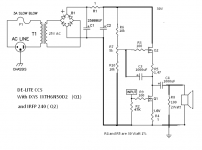
Well the post 605 shows the amp with the upper part with an enhancement mode device , which is the IRFP240 or the IRFP 044 of course - . The lower part is self biased by the depletion mode Mosfet and the Power Resistor . So looking at it , we see that there isn't the typical feedback or loop resistor to set the bias .
Though , the music is quite a bit ...let's say different (?) 😉 regarding the version when both gain devices are enhancement mode .
Oh the amp doesnt have thumps at turning on to worry about , but here there is tons of filtering 😀
Last edited:
- Home
- Amplifiers
- Pass Labs
- Pass "DeLite" Amp from BAF