I hope it is not a problem to also make new thread about my problem with 1212m. So here is post again:
Hello,
I have 1212m rev 1 with FW port.
Looks like nice sounding card.
Anyway, in the last time, i have problem with one channel.
I'm using the cards analog outputs, unbalanced, and connected to the int amp CD input.
Anyway, problem is that the left channel has become obviously quieter than the right channel! Id say about 20db quieter. What can be the problem, please?
I experimented a little, and found out that when I take left TS connector and pull it about 1/2 inch out of the card, the sound becomes OK level. So, i would say that when using left TS the sound is attenuated about 20db but if using RS the sound is OK. On the right channel, the sound is the same level if the connector is fully put into the card (TS) as it is if I pull out connector about 1/2inch so it uses RS signal. I hope to help you with this to help me find a problem.
Also, I measured voltage on the outputs: right TS and RS have about 0mV while left RS have also 0mV but left TS have about 20mV.
Please, thanks for help.
Ja bih ti rado pomogao, ali...
It is hard to comment on what seems to be ether intermittent problem or I would say weird problem. DId you try to seat that card better? That reminds me to a problem I had with memory. Once I had some weird problems with the computer and I discovered it to be the memory problem. I pulled the memory out and cleaned contacts first with alcohol and than with simple rubber eraser (sa gumicom) Than I placed it back and made sure it is seated well.
In your case that is the first thing I would try. Next I would clean with contact cleaner all audio connectors. That might solve the problem.
Bets luck, and let us know if it worked.
Last edited:
Thanks God.....or better say AR2 😉
No, that is not the problem.
I believe the problem is in the analog board.
Im not good at electronics, but believe like some cap, or opamp or resistor, or some other component has lost its specification.
My english is not very good, but im afraid you dont understand my problem in the first post.
I measured with the voltmeter accross output connectors and all are fine (0mv) except left TS where is 20mV. So, it is some defective component, i would say. Or worn out. My PC has many many work hours! During the year it is way more ON than OFF. And the 1212m is 3 years with me.
Anyway thanks for helping.
Also, I believe that schematic of the analog board would help me find an issue.
I am little bit confused here:
" Also, I measured voltage on the outputs: right TS and RS have about 0mV while left RS have also 0mV but left TS have about 20mV."
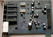
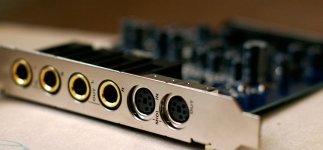
How many outputs are there? Two or more? 20mV of DC offset does not need to be any indication, so lets not get stuck on that. My question is: What kind of output signal is coming out of your card - balanced or single ended? Do you use RCA, mini jacks or banana connectors? Could you make a picture of your card and connectors please.
Yes. Card has 2 TRS outputs (L and R). They are mono, (either) balanced/unbalanced outputs. So every output has actually 2 signals, one of wich is inverted (balanced output). So, on the output that is working ok, both signals ( TS and RS) are 0mV. On the other output TS has 20mV and RS is also 0mV. And when I put the male plug into the card, the output is very quiet. But If I pull out the plug about 1cm, so it connects to RS, the output is ok.
I will put a photo in a moment.
I will put a photo in a moment.
Last edited:
Do you have scope or even some measurement application?
It could be that there is a problem with one half of the balanced signal. What would be very helpful is to use ether scope or app and to manually connect one half and to ground other half of the balanced signal. If you are using app, than you could just loop signal. For that you will need to make your own cable - with balanced connectors (as long as if your input is balanced as well, which I assume it is) Than produce a simple sine way and see what level are you getting for each half of the balanced signal. That way we could get some closer in finding what is going on.
It could be that there is a problem with one half of the balanced signal. What would be very helpful is to use ether scope or app and to manually connect one half and to ground other half of the balanced signal. If you are using app, than you could just loop signal. For that you will need to make your own cable - with balanced connectors (as long as if your input is balanced as well, which I assume it is) Than produce a simple sine way and see what level are you getting for each half of the balanced signal. That way we could get some closer in finding what is going on.
No, no osciloscope nor program. But I believe I can find application on the net. TrueRTA free is ok?
Yes, it looks like a problem with one half of balanced signal!
Actually, I am using non-balanced output, because Im using card's outputs as a source for my hifi amplifier.
Inputs are balanced/unbalanced, you are correct.
Im only not sure about the procedure: I have a balanced cable (TRS to TRS) 3m long. Is it OK for the measurment? I need to connect the problematic output to the one of the inputs and than measure with the application?
Last edited:
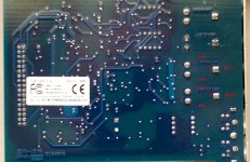
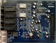
Red circle, that green wire on ADC is really funky thing. Green circle is your DAC. Blue circle is your analog output. Lets start with measurement on connectors. Next will be measurement on those transistors and opamps if you can. As you could see there are just a few parts in the output.
Attachments
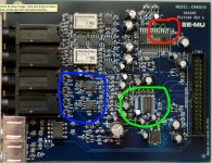
That green wire is, some in-factory fix of the ADC. I bought the card new and it came like that.
Installed TrueRTA.
What to measure?
Installed TrueRTA.
What to measure?
That green wire is, some in-factory fix of the ADC. I bought the card new and it came like that.
Installed TrueRTA.
What to measure?
Yes, I figure that out. But it is a funky thing that they realized they need to have that connection after they made boards. Cool, it makes view DIY friendly,
😛
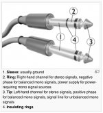
Ok what to measure - check my previous post. Make yourself a cable that has two balanced connectors on each end. Than three wire - tip is your positive, first ring is negative and body - sleeve is ground. First wire each side just like that. Plug in both sides - make loop - in to out. Send 1Khz sinusoidal signal and measure output of each channel. That way we could determine exact difference between channels. Than do your thing - pill that plug half way and see what you are getting level wise.
Next, take jumper wire and apply it on one connector only. First connect tip and sleeve. Than measure. Next connect Ring and Sleeve. Measure. If all is OK there should be difference between balanced and any single ended measurement of 6dB. To apply wire the easiest way to do it is if you have jumper wire with spring clips at the each end. If not just solder where you will keep one side soldered on ground, and you will solder and unsolder the other side.
Attachments
Thanks. At first it looked over-complicated for me, but after reading few more times, I understand and I can do it.
I have troubles running analyzing software on my windows 7. Im not sure if it is because of w7 or because of EMU's beta drivers for w7. Tried both TrueRTA and RMAA. Expecting to resolve the problem. Will try to use my 3m balanced cable, instead of making one? I can pull of the insulator from the cables connectors at both ends to be able to use jumper wire for the second part of the testing.
One question: for the first part of the testing (first paragraph in your last post), should I use the same INPUT for both channels and all testings, or test L output with L input and R with R?
Thanks. At first it looked over-complicated for me, but after reading few more times, I understand and I can do it.
I have troubles running analyzing software on my windows 7. Im not sure if it is because of w7 or because of EMU's beta drivers for w7. Tried both TrueRTA and RMAA. Expecting to resolve the problem. Will try to use my 3m balanced cable, instead of making one? I can pull of the insulator from the cables connectors at both ends to be able to use jumper wire for the second part of the testing.
One question: for the first part of the testing (first paragraph in your last post), should I use the same INPUT for both channels and all testings, or test L output with L input and R with R?
Ideally use only one input so that we minimize variables. When using RMAA, you need to make sure that you are in mono mode of testing. Secondly I am not sure if RMAA will allow you to mix input and output channels. I believe it should, but if it doesn't than use L out on Left in and R out on R in.
RMAA is pretty much self runing program that does not give you much options to adjust. You would be in much better shape of using something like Spectra Scan or simillar. Also I am not too familiar with TrueRTA.
Good luck
Ok.
Here are first 2 shots. First is from problematic right channel and second is from left channel.
I post this to tell me if this is the measurement that i need to do. Do you need any other measurement or other info?
Both outputs were connected to the same (right) input. In the PatchMix (it is emu's application) i choose RMAA session.
About your last question, you wont stop helping if I say ? 😉
Im just kidding, it is from Srbija.
Here are first 2 shots. First is from problematic right channel and second is from left channel.
I post this to tell me if this is the measurement that i need to do. Do you need any other measurement or other info?
Both outputs were connected to the same (right) input. In the PatchMix (it is emu's application) i choose RMAA session.
An externally hosted image should be here but it was not working when we last tested it.
An externally hosted image should be here but it was not working when we last tested it.
About your last question, you wont stop helping if I say ? 😉
Im just kidding, it is from Srbija.
Last edited:
- Home
- Source & Line
- Digital Line Level
- Emu 1212m problems