Hello everyone
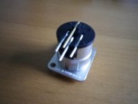
I bought this Neutrik PCB mount 3 pole XLR plug from Premier Electronics. The XLR plug has 4 pins. As far as I know #1 pin should be connected to GND, #2 to Cold & #3 to Hot but I have no idea about #4 therefore would anyone please tell me what is the function or connection of the # 4 pin of this plug?
Thanks.
Attachments
Hello everyone
I bought this Neutrik PCB mount 3 pole XLR plug from Premier Electronics. The XLR plug has 4 pins. As far as I know #1 pin should be connected to GND, #2 to Cold & #3 to Hot but I have no idea about #4 therefore would anyone please tell me what is the function or connection of the # 4 pin of this plug?
Thanks.
That is actually a PC board mount jack so it will be a bit inconvenient to connect wires to. Pin 4 is the outer shell of the connector and it's generally connected to pin 1.
BTW in the US pin 2 is considered 'hot' and pin 3 'cold' but it's only a problem if the phase is reversed accidentally.
G²
Pin 4 would use a second shield or a drain wire to connect the two chassis together.
Pin 1 should be tested to exclude the Pin1 problem
Pin 1 should be tested to exclude the Pin1 problem
That is actually a PC board mount jack so it will be a bit inconvenient to connect wires to. Pin 4 is the outer shell of the connector and it's generally connected to pin 1.
BTW in the US pin 2 is considered 'hot' and pin 3 'cold' but it's only a problem if the phase is reversed accidentally.
G²
Hi stratus
Thank you very much for your inputs. Yes I need the US connection therefore I will correct the pins to read as:
Pin 1: Gnd
Pin 2: Hot
Pin 3: Cold
Pin 4 would use a second shield or a drain wire to connect the two chassis together.
Pin 1 should be tested to exclude the Pin1 problem
Hi Andrew
Thank you very much for your inputs too. But I do not surely understand what do you mean two chassis and what is pin 1 problem. Please give more details.
Thanks in advance.
Pin #1 is NOT connected to Audio Ground.
Pin #1 is NOT connected to Power Supply Ground.
Pin #1 is connected to the Chassis with a very short wire.
Pin #1 is NOT connected to Power Supply Ground.
Pin #1 is connected to the Chassis with a very short wire.
The pin 1 problem Andrew mentioned has caused many a problem with RFI or ground loops. My favorite explanation to pin 1 problems is found in Rane's Handbook.
Grounding and Shielding Audio Devices
Grounding and Shielding Audio Devices
The pin 1 problem Andrew mentioned has caused many a problem with RFI or ground loops. My favorite explanation to pin 1 problems is found in Rane's Handbook.
Grounding and Shielding Audio Devices
Hi Gray
This is a very good and clear diagram for wiring. Thank you for attach it here.
In this diagram, it has singal and chassis grounds, in addition, there will be a power ground, therefore there will have 3 grounds in an amplifier. Would anyone please correct me if I am wrong?
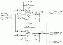
Yes, there appears to be a junction dot that should not be there between Input Signal and Signal Ground.
Personally I'd use lower value build out resistors - maybe 27 rather than 120 ohms and also delete the capacitors - but that's just me.
G²
G²
Yes, there appears to be a junction dot that should not be there between Input Signal and Signal Ground.
Hi imix500
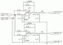
I re-draw the schematic but I am not sure if it is correct or not. Please comment. Thanks
Attachments
Personally I'd use lower value build out resistors - maybe 27 rather than 120 ohms and also delete the capacitors - but that's just me.
G²
Hi stratus
What would be the different if change resistor value from 120 Ohm to 27 Ohm in this circuit? Please advice.
I do not feel comfortable with the 47uF capacitors too but as far as I know they are coupling capacitors for blocking the DC at output stage, deleting these capacitors probably will create a DC voltage to harm the power amplifier and speakers. What do you think?
I still see the XLR output pin #1 connected to audio (circuit) ground.
Pin #1 is not part of the audio circuit, it only connects to the chassis/enclosure. And then with a 2cm (or less) wire.
Pin #1 is not part of the audio circuit, it only connects to the chassis/enclosure. And then with a 2cm (or less) wire.
I still see the XLR output pin #1 connected to audio (circuit) ground.
Pin #1 is not part of the audio circuit, it only connects to the chassis/enclosure. And then with a 2cm (or less) wire.
For my own use I use a low value resistor in the ground line. Most ground loop _Voltages_ are quite low but the currents can get high. A 10 ohm resistor in the ground line will drop those currents dramatically. Don't worry about hum. That's why you have balanced audio.
G²
- Status
- Not open for further replies.
- Home
- Amplifiers
- Solid State
- Wiring a XLR plug