I tried 1.5 ampere transformer 24v for power supply for preamp almost finish,and it works great when only use it for each parts as supply, but when I change it to 24v 15 ampere transformer it give me high hum but that necessary for all together.
well the needed to high ampere transformer is to get suitable power supply that handle these:
- LM3886 single chip
- TDA7294 single chip
- EQ 10 band
- X- cross filter.
- TDA7294 dual bridge mode.
what could you suggest me to use single power supply for each of them or the 15 ampere transformer I have and then get power supply for all of them?
I just want to make sure the hum is gone, my grounding is surely working I check everything, what could else be the problem that reduce the hum all the way?
Sounds like it's not the transformer that's the problem, but inadequate power supply filtering or stabilization. Can you post a schematic of the power supply and the calculated power requirements (i.e. how much current will be drawn from which voltages)?
Sometimes if you cut the earth wire the hum sound dissapears...You will have to experiment a little...
Are you in Syria or Canada?
Also as mastodon posted it would be better to post scematic to make sure everything
is ok from the power supply
Are you in Syria or Canada?
Also as mastodon posted it would be better to post scematic to make sure everything
is ok from the power supply
I use this for power supply in general for all

more explanation:
TDA single use single power supply 24v 1.5A transformer+10A bridge+4700uf/50v x4+220nf ceramic capacitor as filtering part.
TDA dual use single power supply 24v 3A transformer+10A bridge+4700uf/50v x4+220nf ceramic capacitor as filtering part.
LM single use single power supply 24v 3A transformer+10A bridge+2200uf/50v x4+100nf ceramic capacitor as filtering part.
EQ use single power supply 15v 1.5A transformer+10A bridge+2200uf/50v x2+100nf ceramic capacitor as filtering part.
X-Cross filter using the same power supply for LM.
all working great alone if they each have one power supply, combination making the problem.
I wish to make this work, but I don't know where is the problem come from the power supply part or the transformer itself.
it both hum sound with input or without it, for the input I use the same ground point with power supply.
Attachments
for the schematic its in the picture I could help with more if you need but its temp power I used in temp fiber not 100% finish.Sounds like it's not the transformer that's the problem, but inadequate power supply filtering or stabilization. Can you post a schematic of the power supply and the calculated power requirements (i.e. how much current will be drawn from which voltages)?
for calculated its in previous post.
now I"m in Syria and I did experiments on the power with multi meter and it give right voltage for output power requirement.Sometimes if you cut the earth wire the hum sound dissapears...You will have to experiment a little...
Are you in Syria or Canada?
Also as mastodon posted it would be better to post scematic to make sure everything
is ok from the power supply
both I have hum but its disappear when load come I mean full load you then could not know if there is still hum or not but when music stop even for 0.5s then it come back.Also , do you have hum sound with the input plugged in?or without?
for input I test 4 types: PC sound card - Laptop headphone output - Cell phone headphone output - Ipod.
I still facing this problem now I think I'll try to use regulator for more filtering hope this help.
Hosam,
you cannot use a centre tapped transformer with dual bridge rectifiers to create a dual polarity power supply.
Either use a dual secondary or use a single bridge rectifier.
Assemble a mains light bulb tester.
Plug in every new or modified mains powered project to the tester to prove you have not made a mistake.
You will find that the bulb lights up when you plug in your transformer with that rectifier arrangement.
BTW,
the hum from the transformer is the wires vibrating when passing hundreds of amperes.
You will very quickly burn out your transformer playing with it like this !!!!!!
You are the most dangerous of all DIYers. You don't realise enough to know when there is a danger to your life or limb !
Last edited:
you're correct in one way and wrong in the other. for center tap I'm sure it has problem that's why I ask in the main topic header for help with transformer itself. but I don't have toroidal to use instead of center tap type.Hosam,
you cannot use a centre tapped transformer with dual bridge rectifiers to create a dual polarity power supply.
Either use a dual secondary or use a single bridge rectifier.
Assemble a mains light bulb tester.
Plug in every new or modified mains powered project to the tester to prove you have not made a mistake.
You will find that the bulb lights up when you plug in your transformer with that rectifier arrangement.
BTW,
the hum from the transformer is the wires vibrating when passing hundreds of amperes.
You will very quickly burn out your transformer playing with it like this !!!!!!
You are the most dangerous of all DIYers. You don't realise enough to know when there is a danger to your life or limb !

Note: I'm not suggest this build for anyone doesn't have experience at all if I take your words about dangerous part of this one.
so the hum here come from wire vibrating so how can I solve this part?
do you think vibrating could solve if I use two diodes and 680ohm resistor with 100nf to the ground?
and for safety consider I use 5A fuses one both channels before the bridges they didn't blow up at all is it still danger to use in such a way?😱
for the equipments I use separated power for each one I mention that before and I repeat it again, but problem comes with combination part and I want to make that because my amp case is small and can't handle all of them together can you suggest me best way to make power supply that handle all mention above with safety consideration? 😕
Hi,
it does not matter one iota that it is an EI, or a toroid, or an Rcore, or a Ccore.
What matters is that you have used a dual bridge on a centre tapped secondary to create a dual polarity PSU. That does not work.
It will overheat your transformer and given long enough will burn it out. If the overheated primary starts to short out, there is potential for an explosion. The "energy" available from the mains before the fuse or MCB opens is enormous !!!!!
Assemble that bulb tester and stop arguing.
ok I'll post it when finish with bulb test to make sure everything is safe enough, but again I need the solution for the major problem one power instead of multi power...
use a single bridge rectifier with a centre tapped transformer.
Do not plug it in direct to the mains.
ALWAYS test it first by plugging into your bulb tester.
Do not plug it in direct to the mains.
ALWAYS test it first by plugging into your bulb tester.
You can use a centre tapped transformer to produce split rails but NOT as you have it connected.
Connect the two ends of the secondary (top and bottom) in your diagram to the AC terminals on one bridge rectifier. The + and - provide the split rails. the Centre tap of the transformer is then 0V and the output filter capacitors need to be connected between + and 0V and - and 0V.
Connect the two ends of the secondary (top and bottom) in your diagram to the AC terminals on one bridge rectifier. The + and - provide the split rails. the Centre tap of the transformer is then 0V and the output filter capacitors need to be connected between + and 0V and - and 0V.
Hosam,
you cannot use a centre tapped transformer with dual bridge rectifiers to create a dual polarity power supply.
Either use a dual secondary or use a single bridge rectifier.
Assemble a mains light bulb tester.
Plug in every new or modified mains powered project to the tester to prove you have not made a mistake.
You will find that the bulb lights up when you plug in your transformer with that rectifier arrangement.
BTW,
the hum from the transformer is the wires vibrating when passing hundreds of amperes.
You will very quickly burn out your transformer playing with it like this !!!!!!
You are the most dangerous of all DIYers. You don't realise enough to know when there is a danger to your life or limb !
Please explain to this newbie what a "mains light bulb tester" is. Thanks.
I did this exactly this part of power but I don't have program to draw this PCB specailly I only have temp fiber to check it. so I use simple picture only to clear the idea maybe its my problem to be not so clear in parts sorry for that.You can use a centre tapped transformer to produce split rails but NOT as you have it connected.
Connect the two ends of the secondary (top and bottom) in your diagram to the AC terminals on one bridge rectifier. The + and - provide the split rails. the Centre tap of the transformer is then 0V and the output filter capacitors need to be connected between + and 0V and - and 0V.
so to be more clear:
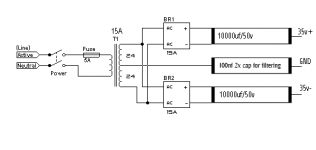
parts used after the transformer in picture: 15A 2x bridge, 2x 10000uf/63v capacitor, 2x 100n ceramic capacitor, 2x fuses 5A slow.
- bridge1 15A connected in ~ with the the dual red cable from the transformer and - connected to first rail of filter cap - and the other one connected to + of the same one.
-bridge2 15A connected the same as bridge1 with the second rail of filter cap.
- the 0 black cable from the transformer is connected to the + of the capacitor in both rails 10000uf/63v and 100n cap.
- filter ceramic 100n first one connected one part to 0 black and the other part with first - 10000uf/63v.
- filter ceramic 100n second one connected one part to 0 black and the other part with the second - 10000uf/63v.
- first fuse after the - of first rail cap, second fuse after the - of the second rail cap.
at the end the meter give me result 38v DC from the connection after the capacitor filter in - part. I make the test with no load or any connected amp to it.
hope this clear the idea anyway thanks for explanation I was wired its really bad way of power supply and it will cause the hum issue.
A dual (two) bridge rectifier only works with a dual secondary when creating a dual polarity PSU.
A centre tapped transformer must use a single (one) bridge rectifier to create a dual polarity PSU.
A centre tapped transformer must use a single (one) bridge rectifier to create a dual polarity PSU.
well if use junction to take the power source then does one bridge handle the load?
I mean if they are all under the transformer ampere and under the bridge ampere.
for the part of humming from the wires how can I erase these?
I mean if they are all under the transformer ampere and under the bridge ampere.
for the part of humming from the wires how can I erase these?
Have you assembled the bulb test YET ?
Does the bulb light up, or glow dimly, or not glow at all, when you plug in your faulty wiring?
Does the bulb light up, or glow dimly, or not glow at all, when you plug in your faulty wiring?
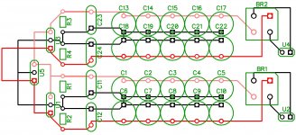
now here is a picture I draw with DipTrace free program. tell me if you think this still wrong one before I do more test please.

black connected directly to transformer, Red1 + , Red2 -. for the bridge two are connected to transformer 15A
Cap all rated 2200uf/63v except for 100nf with different type ceramic.
black connected directly to transformer, Red1 + , Red2 -. for the bridge two are connected to transformer 15A
Cap all rated 2200uf/63v except for 100nf with different type ceramic.
Attachments
Last edited:
you still have dual bridge rectifiers.
Use one bridge rectifier when you use a centre tapped transformer.
Use one bridge rectifier when you use a centre tapped transformer.
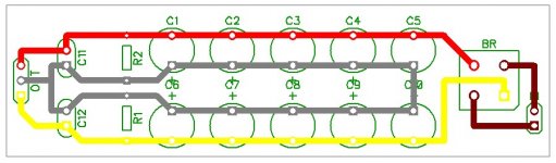
thank you to be patience and understandable of my multi posts here, for now its working with one bridge this is what I did with it:you still have dual bridge rectifiers.
Use one bridge rectifier when you use a centre tapped transformer.
but I still have question if you don't mind is this one good for handle load one the preamp I post before? or do you think its enough and good one?
do I need to use regulator for filter DC output?
after measurement the power supply give 38V DC without load.
Attachments
- Status
- Not open for further replies.
- Home
- Amplifiers
- Power Supplies
- suggestion needed for transformer