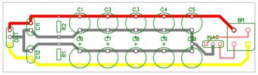
The transformer centre tap must be connected to the Zero Volt Rail.
I consider the best place for that connection to be right above the C10 label, between the first two capacitors.
This same connection must also be taken to the chassis.
The chassis must have a permanent Safety Earth that connects to third wire in the mains supply cable (PE).
This PE must go back to the distribution board without any breaks.
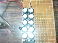
ok now I try this fixing with PCB hope this one is correct and for Earth grounding I use same cable from the transformer that ground 0 I suppose its ok but if not what I should do to keep it more safer as this board seems extremely charged and danger even with fuses.The transformer centre tap must be connected to the Zero Volt Rail.
I consider the best place for that connection to be right above the C10 label, between the first two capacitors.
This same connection must also be taken to the chassis.
The chassis must have a permanent Safety Earth that connects to third wire in the mains supply cable (PE).
This PE must go back to the distribution board without any breaks.
Attachments
Hosam,
Asalam Aleikum, Marhabba,
The picture you attached is not so clear.
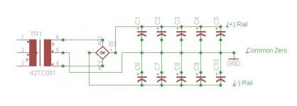
A proper schematic is attached below.
Pleas note that if you need +/- 45Volt, the transformer should be around 90Volt center tapped, because of each rail (the positive rail and the negative rail) will get 1/2 of the voltage between the (+) and (-) terminals of the bridge rectifier.
Asalam Aleikum, Marhabba,
The picture you attached is not so clear.
A proper schematic is attached below.
Pleas note that if you need +/- 45Volt, the transformer should be around 90Volt center tapped, because of each rail (the positive rail and the negative rail) will get 1/2 of the voltage between the (+) and (-) terminals of the bridge rectifier.
Attachments
NO !!! 90Vac centre tapped will give ~+-65Vdc.........if you need +/- 45Volt, the transformer should be around 90Volt center tapped,
Last edited:
NO !!! 90Vac centre tapped will give ~+-65Vdc
I stand corrected. The transformer's secondary should be around 57Volt AC, center tapped. That is, a secondary of 0-28.5-57Volt AC. 45Volt AC secondary will get +/- rails of about 35Volt DC.
You can use a centre tapped transformer to produce split rails but NOT as you have it connected.
Connect the two ends of the secondary (top and bottom) in your diagram to the AC terminals on one bridge rectifier. The + and - provide the split rails. the Centre tap of the transformer is then 0V and the output filter capacitors need to be connected between + and 0V and - and 0V.
An externally hosted image should be here but it was not working when we last tested it.
It's really straightforward.
after build this power supply now things get complicated because I get 55v DC from it and I'm afraid that I could fire the TDA7294 cause it could handle without load only max 50v so any suggestion to down the extra 5v or it could work with it?
In the case of TDA7294, which draws so little current in quiescent mode (no signal) and so much current under full output power, the only option I see is to change the power transformer.
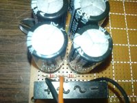
now its working great even with load give me 36v picture at attachments, thank you all for your help.
for parts I used Transformer 15A 24-0-24 AC, 2200uf/50v x10, 100nf ceramic x2, 22k 1W x2,bridge 15A 600v.
for parts I used Transformer 15A 24-0-24 AC, 2200uf/50v x10, 100nf ceramic x2, 22k 1W x2,bridge 15A 600v.
Attachments
- Status
- Not open for further replies.
- Home
- Amplifiers
- Power Supplies
- suggestion needed for transformer