Well, maybe I should go back and put 2 x driver transistor and bias transistor on the same heatsink, seperate from the output transistor heatsink. Been reading a little about it and the bias transistor should sense the driver transistors only, and not the output transistors.
It wont take much to make that change.
It wont take much to make that change.
Well, maybe I should go back and put 2 x driver transistor and bias transistor on the same heatsink, seperate from the output transistor heatsink. Been reading a little about it and the bias transistor should sense the driver transistors only, and not the output transistors.
It wont take much to make that change.
I've just been thinking of posting about that - I didn't like that either. Why not leave them where they are, vertically mounted onto an aluminium plate?
In fact, I'm not sure even about forcing drivers in EF stages to follow the OP temperature. It is often done, but is that merely for ease of consruction?
Personally, being a DIY pcb fan, I don't like double sided PTH boards. A relatively simple schematic like this is easily manageable on a single sided layout, with links if needed. It may be less costly.
Is Rod's board double sided?
Brian
Well, it probably is easier to just put eveything on one big heatsink, but whether it is optimal or not is the question.
Doublesided is not an issue, going to get the PCB's professionally made.
Rod's boards are singlesided.
Well, this should be my final version.
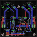
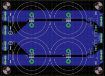
Drivers and bias transistor will be thermally coupled through a small piece of aluminium for optimal thermal tracking. Made space between them and the output transistors so they arent too close to the L shaped bracket holding the output transistors and to the main heatsink.e power supply PCB instead.
Reduced the overall board size to a smaller 10 x 10 cm format.
Removed the fuseholders, they will be on the power supply PCB instead.
Only have to fix the silkscreen a little.
Attachments
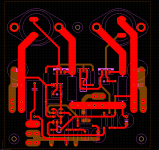
Wasnt entirely happy, so went back and made a few layout changes, including going from a 4.7uF input to only 2.2uF, thats still a -3db point of around 3.5hz, more than enough.
Madeit more compact in some areas, which reduced the length of some of the traces, it also ment better placement of certain components.
Imo, this new layout is overall better than the last one.
Also theres room for fuseholders again, as per the original P3A schematic.
Madeit more compact in some areas, which reduced the length of some of the traces, it also ment better placement of certain components.
Imo, this new layout is overall better than the last one.
Also theres room for fuseholders again, as per the original P3A schematic.
Attachments

Last edited:
...Doublesided is not an issue, going to get the PCB's professionally made...
I'd etch at least one first and build it as a prototype, just to confirm it all works/fits as planned.
Yes, I have the tee-shirt! 😀
I'd etch at least one first and build it as a prototype, just to confirm it all works/fits as planned.
Yes, I have the tee-shirt! 😀
Maybe, maybe not. I like taking chances. 😀😎

I'd etch at least one first and build it as a prototype, just to confirm it all works/fits as planned.

It wouldn't take much extra work to make it single sided with a jumper or two (if any).
It wouldn't take much extra work to make it single sided with a jumper or two (if any).
Yup, at a very quick glance I could get it down to three, and that's without any major thought.
I played with layout of another simple design
I decided to try double sided board
I arranged, rearranged, over and over
trying to make it better, more logic
spent several weeks doing just that
and you know what ?
in the end suddenly double sided made no sense at all
not needed really
no jumper either
honestly, I think hardwired veroboard would be even better
The first versions were singlesided, but too big a compromise wrt component placement, track length and track routing. Hence the doublesided versions.
Making it singlesided in itself is not an issue.
Making it singlesided in itself is not an issue.
double sided without through hole plating is different, yes ?
some components can only be soldered from one side, like electrolytics
some components can only be soldered from one side, like electrolytics
On a 10cm x 10cm board, 25% of which is consumed by two TO-3's, trace length really isn't an issue...
On a 10cm x 10cm board, 25% of which is consumed by two TO-3's, trace length really isn't an issue...
I could put the TO-3's off board and use wire to connect them to the board, but they would most likely be just as long as the current pcb tracks going to them. 35 mm of the top of the pcb is going to be occupied by a L bracket. A not unusual way of mounting TO-3's to a heatsink. 🙂
Last edited:
double sided without through hole plating is different, yes ?
some components can only be soldered from one side, like electrolytics
Your point being?
Like I said, Im going to get a pcb house to do my boards.
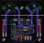
The white line shows how far in the L bracket will go and then theres just enough room for a small piece of aluminium attached to the drivers and bias sensing transistor, for thermal coupling and thermal tracking as usually required for a CFP output stage.
I could move the output stage a little closer, maybe 5mm without the L bracket and thermal coupling/sensing heatsink getting too close.
I could move the output stage a little closer, maybe 5mm without the L bracket and thermal coupling/sensing heatsink getting too close.
Attachments
Last edited:
Changes
Just couldnt leave the layout as is.
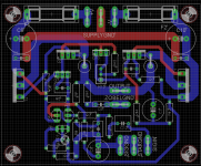
Redid it, now with the recommended MJL4281A/MJL4302A output transistors.
The board is relatively small at 75 mm x 94 mm and it will fit in a 2U Pessante Dissipante case from Modushop.biz
Add my own supply PCB with offboard rectifiers, one board pr channel.
Transformers will be 2 x 25VAC and 225-300VA pr channel.
Considering a Vellemann K4700 DC output protection circuit.
Should be a decent amp once finished.
🙂
Just couldnt leave the layout as is.
Redid it, now with the recommended MJL4281A/MJL4302A output transistors.
The board is relatively small at 75 mm x 94 mm and it will fit in a 2U Pessante Dissipante case from Modushop.biz
Add my own supply PCB with offboard rectifiers, one board pr channel.
Transformers will be 2 x 25VAC and 225-300VA pr channel.
Considering a Vellemann K4700 DC output protection circuit.
Should be a decent amp once finished.
🙂
Attachments
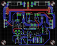
C1 & C2 should be right next to the power output devices. Just far enough away so they don't run hot.
Hmm, does it really matter that much?
But switching places with the 2 x 470uF electrolytes is easy enough.
Edit : Done.
But switching places with the 2 x 470uF electrolytes is easy enough.
Edit : Done.
Attachments
Last edited:
- Status
- Not open for further replies.
- Home
- Amplifiers
- Solid State
- ESP P3A