I saw this in a recent email from Linear Tech -- the LMT8033 is a buck converter module 3.6 to 36Vin, 0.8 to 24V out @3.6A-- very low radiated noise. Adjustable per usual:
http://cds.linear.com/docs/Datasheet/8033f.pdf
http://cds.linear.com/docs/Datasheet/8033f.pdf
ah yes- complete with a table outlining componet values for various voltages. The are really making it easy. Thanks Jackinni - many uses I say.
Nothing a simple groupbuy could not fix. 🙂. Presoldered to some pcb...et voila.Yeah..... Good luck soldering that one.
Forgive me though for asking this. But what are the advantages of such a thing? Can it output ac in high freqs?
Or is it more suitable for the preamps in vogue now where you can plug and play dht's with all kinds of filament voltages?
Yeah..... Good luck soldering that one.
~Tom
Yea I know what your mean. And you have a good point. However I could do it. Hot air is the trick.
I think that Jackinni's idea for a fix when filament windings are not avaiable, or not able to produce enough current is the obvious first idea. Anywhere that you need a higher voltage DC from a lower one. I wonder if you could put two back to back and get + and - for a solid state amp? If someone wants to lay out a board and have it built, I will install the parts properly no cost to anyone on the forum. Send me 10 I'll knock it then in one sitting.
Last edited:
Yes, if you take a look at some of SY's designs using the LM317 as a filament regulator, then lifting the filament well above ground for a cathode follower, use this module instead. The switching frequency is in the 100's of kHz.
Bas, if you think it's appropriate for a GB, any number of folks could have them burned and assembled at 6.3VDC, 12.6VDC etc for mounting on a couple of molex 0.100" headers.
Bas, if you think it's appropriate for a GB, any number of folks could have them burned and assembled at 6.3VDC, 12.6VDC etc for mounting on a couple of molex 0.100" headers.
Ken Thats a cool part too. Needs and inductor, but thats not too hard. The first part needs only 2 resistors and 3 caps. I hope this is not a solution looking for a problem in DIY.
Yea I know what your mean. And you have a good point. However I could do it. Hot air is the trick.
I've soldered SMDs with exposed DAP and such with a heatgun. It works alright. I also have access to a METCAL hot air reflow station at work. I *can* do the work. But why? The LMZ-series of SimpleSwitchers from National are way easier to work with. A couple of passives and you're set. Check out the LMZ12003 for example. Or LMZ14203. Easy to solder too. What's not to like?
~Tom
Yep - Those packages are pretty user friendly. 3 resistors and 4 caps. Like 8 parts plus a board and some headers. I wonder how much intrest there realy is?
I like the LTC3789. It can do buck or boost and seamlessly switch between them. Yes the circuit is a bit more complicated but it can power any tube up to 36 volts from any filament winding from 6.3 volts to 30 volts. Just the thing for lighting up those odd ball sweep tubes. The SSOP package can be soldered with a soldering iron and cleaned up with solder wick.
http://cds.linear.com/docs/Datasheet/3789f.pdf
http://cds.linear.com/docs/Datasheet/3789f.pdf
Might have to include a diode or two if it is comming off a transformer secondary. Oh and one more pretty big cap. Oh and some resistors to get it high off of ground. Isnt that the way it goes.
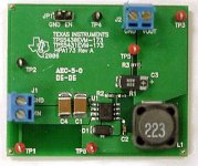
TPS5430EVM-173 Texas Instruments Power Management Modules & Development Tools
http://focus.ti.com/lit/ug/slvu157/slvu157.pdf
11 something bucks at Mouser (What?!?)
Can't believe the loss TI takes to make those EVMs available.
If there is a blue ink "K" on the QC sticker, maybe I tested it...
Exactly the sort of thing I do all day. Then again, not the only
contract mfg competing for the privilege.
I don't have any specific memories of seeing this board.
Copy paste the photo from Mouser...
Attachments
Last edited:
Wait, let me be sure. I'll ask a TI engineer today...
Parametrics on this page say 31V to 1.22V output:
DC/DC Converter (Integrated Switch) - Step-Down Regulator - TPS5450 - TI.com
Both part and EVM spec sheet mention only 5V to 1.22V?
Or maybe I have misread something too quickly.
I might know just who to ask, if he can spare a minute...
Parametrics on this page say 31V to 1.22V output:
DC/DC Converter (Integrated Switch) - Step-Down Regulator - TPS5450 - TI.com
Both part and EVM spec sheet mention only 5V to 1.22V?
Or maybe I have misread something too quickly.
I might know just who to ask, if he can spare a minute...
Both part and EVM spec sheet mention only 5V to 1.22V? Or maybe I have misread something too quickly.
There are output voltage limitations imposed by the maximum duty cycle of 87%. This means that the output voltage can never be greater than 87% of the input voltage. There a few more terms in the maximum output voltage equation. It is on page 13 of the data sheet.
So what happens during startup/shutdown while the input might be above UVLO 5.5V, but less than VOUT?
Last edited:
I got an answer from a guy that usually knows, but only
makes me think I didn't state the question the right way.
I'll just have to buy one and try it. Its not one we built.
makes me think I didn't state the question the right way.
I'll just have to buy one and try it. Its not one we built.
Last edited:
It would have been nice with an externally programmable start-up (soft start) time. Would you happen to know of an eval board in the same price range that offers that?
~Tom
~Tom
So what happens during startup/shutdown while the input might be above UVLO 5.5V, but less than VOUT?
That part is a buck only regulator. The output voltage will ALWAYS be less than the input voltage. There are 2 possibilities and it is not clear in the data sheet which will happen. If the duty cycle is truly limited to 87%, then the output will never be more than roughly 87% of the input (within 1 or 2%). I believe this to be the case here. You will get about 4.3 volts out of this chip with 5.5 volts input.
Many older buck regulators simple saturate the fet if asked to put out more than the input. In this case the regulator bscomes a resistor equal to the RDSon of the fet plus the other resistive losses.
In any buck regulator the efficiency is highest when the input and output voltages are nearly equal. It degrades as the difference between them increases.
The Linear Tech LTC3789 is a buck or boost part. As long as the input is within the allowable range the output will be equal to the programmed value. The output voltage can be below, equal to, or above the input voltage. The efficiency is lowest with low input voltages, and depends on the mode.
Voltage regulators can not create power. THe total power output (voltage times current) will ALWAYS be less than the input power. The difference between the input power and the output power is the efficiency. A linear regulator can have lousy efficiency if the voltage drop is high since it works like a continuously variable resistor.
EXAMPLES:
I have 12 volts and I want to light a 6 volt tube that draws 1 amp.
A linear regulator will drop 12 volts down to 6 volts but the total current will be 1 amp plus a few milliamps to feed the regulator. So the input will be 12 volts at 1.02 amps. the total power input is 12.24 watts to feed a 6 watt tube. 6.24 watts are burnt as heat in the regulator.
A BUCK regulator for this application will have an efficiency rating in the 90% range. This is given in the data sheet, but you will always get a few less percent than they state due to magnetic and switching losses. We need 6 watts for the tube. We assume 90% efficiency so we need to put 6.67 watts into the regulator to get 6 watts out. 6.67 watts at 12 volts is 555 mA. So we will need 555 mA at 12 volts to light up a 6 volt 1 amp tube. Only 0.67 watts will be lost as heat, most of it in the mosfet switch which is inside the regulator in the TI part.
The BUCK OR BOOST part will have a lower efficiency in this case since there are 4 mosfets in the path. You will loose about 1 watt in the above example, so the input current will be about 600 mA.
Lets say you have 12 volts but now want to light up a 24 volt sweep tube that draws 1/2 an amp. You can't get there from here with a linear or buck regulator. You need a BOOST regulator. Again these can be found in the 90% efficiency range at this power level. So a 24 volt 1/2 amp tube eats 12 watts. To get 12 watts out of a 90% regulator you need to put in 13.33 watts. So we need 12 volts at 1.11 amps to light up a 24 volt 1/2 amp tube. 1.33 watts are lost as heat.
Again the BUCK OR BOOST part will have a lower efficiency. so you need to feed it 1.2 amps or so.
I hope this explanation clears up a few things. Briefly you need a BUCK regulator when the output is lower than the input. You need a BOOST regulator when the output voltage is above the input voltage. Neither type of regulator works well when the input voltage is equal to the output voltage, and should not be used whan that possibility may exist over possible operating conditions. The BUCK OR BOST regulator works here and is the universal solution at the expense of efficiency and complexity.
- Status
- Not open for further replies.
- Home
- Amplifiers
- Tubes / Valves
- Omit the filament windings -- LTM8033 from Linear