I was thinking of you putting the meter leads into choc block and running wire from the block to the PCB, just tag soldering where we need to measure.
That's totally hands off measuring, zero risk.
That's totally hands off measuring, zero risk.
Getting nothing across those caps (C801/805)...
Looking at the diagram, the AC to the bridge rectifier comes via C809 (checked and OK), and the other end from that relay. Since that relay is not closing it's not surprising I'm not getting anything out the other side?
- J
Looking at the diagram, the AC to the bridge rectifier comes via C809 (checked and OK), and the other end from that relay. Since that relay is not closing it's not surprising I'm not getting anything out the other side?
- J
Last edited:
I was thinking of you putting the meter leads into choc block and running wire from the block to the PCB, just tag soldering where we need to measure.
That's totally hands off measuring, zero risk.
Ahaaa! Cunning plan Mooly. I shall do that!

Thanks.
First switch off and pull the plug out.
Wait a few moments and feel the resistors across those caps with one finger. Are they warm ? or cold ?
Remember it may be the meter leads not making a good contact. My feeling is that the voltage should be there 🙂
We'll leave it there for now... you keep having a measure and try and follow the continuity of it all.
First switch off and pull the plug out.
Wait a few moments and feel the resistors across those caps with one finger. Are they warm ? or cold ?
Remember it may be the meter leads not making a good contact. My feeling is that the voltage should be there 🙂
We'll leave it there for now... you keep having a measure and try and follow the continuity of it all.
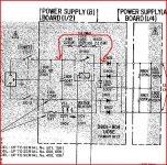
It's the relay - without it closing there is nothing getting into the d801-d804...
R801/802 and the thermal fuse provide continuity. This is the normal "start up" condition before the relay would have closed. Path as shown in red here.
The PSU has to be running before the relay is powered as the relay is powered by the output of the SMPS. Do you see 🙂
The thermal fuse is marked as 10 amp rated on the circuit so hard to believe it could be faulty.
The PSU has to be running before the relay is powered as the relay is powered by the output of the SMPS. Do you see 🙂
The thermal fuse is marked as 10 amp rated on the circuit so hard to believe it could be faulty.
Attachments
If the relay is indeed out of the picture, then logically it has to be R801, F803 or R802 which is faulty then, because no DC is getting out of this PSU board.
I replaced F803 a couple days back as a matter of course (as this is the most common part that fails in these amps) and it tests short so that's fine.
I need to test those two resistors again.
P.S. what is the point of the relay then if the R801/802/F803 are always providing continuity to the rectifying diodes?
It's worth noting that when I bought my TA-F6B there were some blown up caps in my PLPS box and my thermal fuse was open.
It's an interesting circuit--those two resistors sandwich the thermal fuse, so I take it that there was an over-temp condition before there was an over-current event.
It's an interesting circuit--those two resistors sandwich the thermal fuse, so I take it that there was an over-temp condition before there was an over-current event.
It's worth noting that when I bought my TA-F6B there were some blown up caps in my PLPS box and my thermal fuse was open.
It's an interesting circuit--those two resistors sandwich the thermal fuse, so I take it that there was an over-temp condition before there was an over-current event.
That does seem to be the case doesn't it - sandwiched right in between them physically.
I've just tried to measure R801 & R802 (both 2R2 ohms)and get nothing so perhaps I need to desolder a leg on each (without overheating that thermal fuse - tricky?!) and measure them again out of circuit? There's no AC getting into the diode bridge at both ends, so it has to be either something to do with the relay or the resistors/thermal fuse combo.
Shouldn't I also get a continuity reading from R801 through the thermal fuse to R802? I get no reading here either...
Last edited:
OK have desoldered both R801 & 802. Cannot get a reading on either of them so I have to assume they're open. They do look a little grey but I would have thought that's just years of dust and wotnot on the case. Nothing looks wrong externally.
So I guess I need to order a pair of those before I can get started again - drat! Funny how the original thermal fuse wasn't open... I replaced it anyways as it looked quite corroded over time & it might have been on its last legs anyway.
I wonder what fault condition would have taken both of those out but left the thermal fuse OK...?
EDIT: Have ordered a pair of these. They'll JUUSSTTT fit! Ah another wait and more money burned before I can get this thing up and running! Hurrumph! 🙄
AX5W-2R2 5W 2.2 Ohm Cement Resistor x 1 pieces AX5W-2R on eBay (end time 27-Feb-11 09:43:11 GMT)
Last edited:
As I keep saying, the soft start resistors will get HOT quickly, if the relay does not close, either because it's disconnected (in johnm's case) or because of a fault which means there is no output, the thermal fuse quickly blows.
Bypass the relay for further testing. The bulb will do the job of the soft-start. A more modern SMPS would probably use a 10 ohm NTC resistor in place of R801/802 and the thermal fuse. In fact, I'd have probably got a 5 ohm 4.5A NTC to put in there, as they're cheap, designed to withstand being run hot, and will still be out of circuit when the relay closes.
Bypass the relay for further testing. The bulb will do the job of the soft-start. A more modern SMPS would probably use a 10 ohm NTC resistor in place of R801/802 and the thermal fuse. In fact, I'd have probably got a 5 ohm 4.5A NTC to put in there, as they're cheap, designed to withstand being run hot, and will still be out of circuit when the relay closes.
Last edited:
As I keep saying, the soft start resistors will get HOT quickly, if the relay does not close, either because it's disconnected (in johnm's case) or because of a fault which means there is no output, the thermal fuse quickly blows.
Bypass the relay for further testing. The bulb will do the job of the soft-start. A more modern SMPS would probably use a 10 ohm NTC resistor in place of R801/802 and the thermal fuse. In fact, I'd have probably got a 5 ohm 4.5A NTC to put in there, as they're cheap, designed to withstand being run hot, and will still be out of circuit when the relay closes.
Thanks for all that Jaycee - how would I go about jumpering that relay? I think it's the top left yellow to the bottom middle one? Have attached a picture of the connections on the mini-psu board. The points I've marked in yellow are where the relay is connected:
An externally hosted image should be here but it was not working when we last tested it.
BTW the blue and brown wires in the picture are leading off the fuseholder for F801 to the lightbulb holder.
Cheers,
- John
Last edited:
You can solder a jumper wire from where D803 and D804 join, to the Live input on the "AC IN" connector. So, solder from D808/804, below where DANGER is written, to the solder point just to the right of where DANGER is written.
You can solder a jumper wire from where D803 and D804 join, to the Live input on the "AC IN" connector. So, solder from D808/804, below where DANGER is written, to the solder point just to the right of where DANGER is written.
Gotcha! Thanks Jaycee
That means I'll be able to test still even though those two resistors are now desoldered 🙂.
- J
Hi! Sorry for the delay had another zero energy period - grrrrr!
Soldered in that jumper to bypass the relay that Jaycee recommended - all good! Turned on the amp, bulb glows for an instant then extinguishes. Nothing popped on the SMPS 🙂
Measured across C801/805 and get 328VDC. A little higher than it should be, but we're in a high voltage area (quite often around 250V!). I assume this isn't any cause for concern? EDIT: will it be even higher with the fuse replacing the bulb?
So is the next step to measure across D601 (should be approx. 250V?).
- John
Last edited:
That sounds good. Voltage across those caps calculated as Vdc = Vac * 1.414 which gives a nominal 340 vdc from a 240 vac input.
A lot of the voltages in the manual are a bit suspect tbh, or let's just say it's not clear what the test conditions were. So 328v is spot on as a little will be dropped across the bulb. To get 320 volts DC (as shown in the manual) would require an input of 226 volts.... which is (was) the minimum tolerance for UK mains at the time. 240 -/+ 6%
D601 is next... should be around 250 vdc I would imagine.
Lol, you posted as I was typing.
Perfect I would say. It should adjust with the preset pot if you want to try it.
Perfect I would say. It should adjust with the preset pot if you want to try it.
Lol, you posted as I was typing.
Perfect I would say. It should adjust with the preset pot if you want to try it.
Hey Mooly!
Yes indeed it does change when I alter the pot.
What are the next steps then - solder in those four switching transistors, get the clamp fashioned, connected up the output of the SMPS and set for 98-99V as per the manual?
- Home
- Amplifiers
- Solid State
- Sony TA-F6B PSU repair