Development on this project is a bit slow for the summer unfortunately but let it be know I'm not forgetting about it!
I get a lot more of my electronics design work done during the cooler months.
I get a lot more of my electronics design work done during the cooler months.
Are you aware of StormAudio amplifiers?
StormAudio Technology StormFocus
I had a discussion with the company on a french web site, but not possible to know what was inside exactly. There are some patents, I can post here links if some interests.
StormAudio Technology StormFocus
I had a discussion with the company on a french web site, but not possible to know what was inside exactly. There are some patents, I can post here links if some interests.
wow, for some reason i haven't been getting updates on this thread...
while we're on the subject of amps with a low DF, one comes to mind that is more common today than it was just a few years ago, class D amps. actually there are two types of class D amp, those with a feedback loop, and those without, the latter being more common. they're used in everything from sub amps to integrated home theater systems because of their light weight, cool operation and production cost, some of them are very sensitive to variations in speaker impedance "funnies". unfortunately there isn't much that can be done to correct a class D amp without a feedback loop. inserting a feedback loop would require possibly an op amp at the input and lots of filtering of the feedback signal (which might also add unacceptable delay times to the signal).
while we're on the subject of amps with a low DF, one comes to mind that is more common today than it was just a few years ago, class D amps. actually there are two types of class D amp, those with a feedback loop, and those without, the latter being more common. they're used in everything from sub amps to integrated home theater systems because of their light weight, cool operation and production cost, some of them are very sensitive to variations in speaker impedance "funnies". unfortunately there isn't much that can be done to correct a class D amp without a feedback loop. inserting a feedback loop would require possibly an op amp at the input and lots of filtering of the feedback signal (which might also add unacceptable delay times to the signal).
Thanks for finding that, Macleod. It could well be just a brutal resistance variation as in basic variable current feedback designs, in the output stage. I'm thinking there of textbook examples and on Rod Elliott's site regarding that type of design.
'Seems we'll have to check on Duo and see if he's working at it again.
'Seems we'll have to check on Duo and see if he's working at it again.
StormAudio has patented the use of variable damping on class D amp : DEVICE FOR AMPLIFYING A VOLTAGE REPRESENTING AN AUDIOPHONIC INFORMATION
The use of the same principle is patented for any linear amplifier using bridge operation.
The use of the same principle is patented for any linear amplifier using bridge operation.
I am also waiting to hear DUO's project finished, and post something.
I have doing many things since last post here few months ago and playing with power gain. It is finished 200W rated output. Many things funny, big inductors as damper makes my loudspeaker sounds like mixed with something out from small metal can.
The loudspeaker should be driven with current source and additional damper. That's what I've got. Many different sound characteristics are also coming from its damper composition instead of distortion produced. The damper also work in mechanic form while designing box or loudspeaker itself.
There, storm classD, will it be shine or dark. I know that it is slower version, they should have more driving technique.
Last edited:
a while back i released the results of a study i did on what affects output impedance and DF. i've actually been able to do a few of the physical experiments i envisioned. i built a "Howland Current Source on Steroids" with current capabilities up to a few amps (though i use it set to 1A for sake of keeping the experimental data on a 1:1 mathematical relationship as i did in the simulated experiments). i really need to set it up on the test bench again and test it with reactive loads and make sure it's not "squirrely" with capacitive and resonant loads. the pdf of my early ideas and experiments on this can be found here:
http://www.electro-tech-online.com/...4708-ac-ohmmeter-revisited-damping-factor.pdf
http://www.electro-tech-online.com/...4708-ac-ohmmeter-revisited-damping-factor.pdf
Thanks for the PDF, unclejed
The graphs are no color text, but it still readable.
Blameless has higher output impedance(lower DF) at higher frequency, that is the same with my final result. I added capacitor to rise its gain at about 400Hz. That mean less active damper (NFB act as active damper). The different is mine still using resistor connected parallel with the loudspeaker through power gain input (as passive damper) and higher output amplifier impedance.
believe it or not, part of the idea for that paper came from a very old article in EDN or Electronics Magazine on measuring the output impedance of a linear DC voltage regulator... i tend to pick up bits and pieces of things like that and turn them over in my head until i find something useful for them... of course a linear voltage regulator really isn't much different than one half (actually three quarters) of an audio power amp. it has a diff amp (LTP), VAS stage and half of an output stage... to cancel ripple amd noise it has to have a fairly decent frequency response and low output impedance within that frequency response.... think of it this way, with DC, "distortion" is anything that is not DC, so a regulator is a "low distortion" DC amplifier.... just my rather weird way of looking at it...
No single commercial amplifier using it, they must have big reasons. If we know it it must be something helpful.
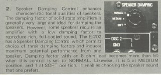
A bit late to the discussion, but I can think of at least one commercial amp with different DF settings---the well regarded Accuphase E-202 of the early 70's. I've attached a clip from the owners manual, showing the DF knob on the back of the amp and the written discussion of its function from the owners manual.
Steve.
Attachments
It would be a shame if those patent applications make it to become real patents... there is absolutely nothing new in there...StormAudio has patented the use of variable damping on class D amp : DEVICE FOR AMPLIFYING A VOLTAGE REPRESENTING AN AUDIOPHONIC INFORMATION
The use of the same principle is patented for any linear amplifier using bridge operation.
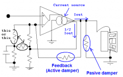
rhe "ideal" solution is to have some way of varying the output impedance of the amplifier without dissipating extra power (inserting a resistor dissipates power). there are two possible ways if doing this: 1) variable open loop gain, and 2) hybrid (voltage and current) feedback. i think hybrid feedback is both the simplest and sonically better than the first. it's simpler because adding variable current feedback to the inverting input of the amplifier doesn't alter the amp circuitry itself, just the feedback loop. it's sonically better because the open loop gain of the amp doesn't change, so the distortion performance isn't degraded. to lower the DF by lowering the open loop gain, would increase distortion (in some applications, this might not be much of an issue, like a guitar amp where a little extra "dirt" in the signal might be desirable to some musicians). lowering the open loop gain is a bit more complicated than just adding a couple of components and a pot (although such an option is possible within certain limits by making the tail current in the diff amp variable but there may be undesirable side effects other than distortion to do it this way).
The hybrid feedback of StormAudio is shown here after :rhe "ideal" solution is to have some way of varying the output impedance of the amplifier without dissipating extra power (inserting a resistor dissipates power). there are two possible ways if doing this: 1) variable open loop gain, and 2) hybrid (voltage and current) feedback.
Facteur d'amortissement max ou impédance de sortie variable? - Amplificateurs
It is equivalent to a voltage generator with a serie resistor :
Facteur d'amortissement max ou impédance de sortie variable? - Page 2 - Amplificateurs
So power is to be dissipated somewhere. If it is not in a serie resistor, it is in the amplifier itself, the output stage.
are we actually dissipating the power or just altering the voltage characteristic of the feedback when you add current feedback? after all, the current is converted to a voltage at the inverting input of the amp and the altered voltage feedback is what changes the output impedance of the amp. the "output resistance" (i.e. the physical output resistance) never changes, just the amplifier's response to variations in load impedance and back EMF from the load. but i don't think there's that much of a change in output device dissipation when lowering the DF of an amp by altering the feedback. we're altering the gain characteristic of the amp here.
There is a "reality" in output impedance as it is possible to measure it the same way.
Your thoughts worth anyway consideration, the efficiency is, as you stated it, higher in the case of an amplifier with modified feedback.
We are still facing the same classB amplifier and there is no reason to change one % to efficiency. (we may argue that, running at lower level, amplifier efficiency is lower in this case. but it is related to output power vs max output power)
You helped me understand that (the basic calculations I did didn't highlight that).
This is my Amplifier result as far, special focused on its damper. It looks waste many power, don't worry, with power gain only some miliwatts wasted on damper and feedback resistor. It just simplified schematic, so power gain is excluded from it.
Hi spind, isn't it is 50's?
Hi spind, isn't it is 50's?
Attachments
Ok, It seems the case, unfortunately and we never got to see any of it. Anyways, in case you haven't seen this before, here is an interesting primer and some ideas to adapt existing amps. for experiments and a little entertainment. The educational aspect is a great benefit for anyone not really sure this is going to work out in their situation. It saved me a lot of cash, too.
Variable Amplifier Impedance
Variable Amplifier Impedance
- Status
- Not open for further replies.
- Home
- Amplifiers
- Solid State
- That curious extra knob, or: "Trans-Amp"