Hi
I have bee looking at crowbar circuits and came across this thread. In it is decribed the dc protection circuit used on the quad 405. It uses a Silicon Bilateral Switch to activate a triac which then shorts the amp out. It also contain a filter network to ensure the thing doesn't trigger all the time.
My question here is simple. What advantage in this instance does the SBS hold over a zener? The only thing that I can see is that it may be a bit more accurate with the "trigger voltage", but surely this voltage does not realy matter.
The reason I ask is that these SBS's are horrendously expensive but at the same time I am convinced that quad must have made this decision for a reason.
Byrd said:Hi
I have bee looking at crowbar circuits and came across this thread. In it is decribed the dc protection circuit used on the quad 405. It uses a Silicon Bilateral Switch to activate a triac which then shorts the amp out. It also contain a filter network to ensure the thing doesn't trigger all the time.
My question here is simple. What advantage in this instance does the SBS hold over a zener? The only thing that I can see is that it may be a bit more accurate with the "trigger voltage", but surely this voltage does not realy matter.
The reason I ask is that these SBS's are horrendously expensive but at the same time I am convinced that quad must have made this decision for a reason.
I think if you replace SBS with pair of zeners in quad style circuit the Triac will never fire. If your triac needs 100mA on gate to fire its never going to happen in quad style circuit. Of course you can scale down some of the resistors to get enough current but you end up with some losses on those resistors and you need way more bigger cap for same filter response. And even then you have the problem of slowly rising triac gate current. I am not sure if it is an issue with triacs but at least BIG SCR's switch faster and more reliably with sharp trigger pulse.
The NTE6403 and the 2N4992 are bringing close to $8 these days. A couple of years back I was paying $0.50 for them. Fortunately, they are just four $0.10 transistors and a couple of zeners. Carver uses this discrete version in most of their magnetic field amplifiers. You can also use the reverse breakdown of a BE junction of an inexpensive transistor instead of the zener, they usually have better match of the breakover voltage that way too.
http://www.onsemi.com/pub/Collateral/MBS4991-D.PDF
http://www.onsemi.com/pub/Collateral/MBS4991-D.PDF
Seems that around 30V diacs are easy to find and cost only cents, but anything less than 30volts is ceased 10 years ago.
Exatly my experience - What about using a "protection IC" to trigger these triacs. It has relay drive capability - 80mA
Prehaps in conjunction with a BTB08-600C triac - these only require 25·00 25·00 25·00 50·00 mA in the respective trigger quadrants.
Prehaps in conjunction with a BTB08-600C triac - these only require 25·00 25·00 25·00 50·00 mA in the respective trigger quadrants.
When I built the Leach amp in the early 80's, I added a protection circuit which does a few things:
1) Thump supression
2) Logarithmic ramping of the audio.
3) Catastrophic amp protection.
4) Slow turn-on because of 40,000 uf of capacitance.
These were prompted by one power supply design where an electrolytic cap on the amp board shorted. It blew one of the rail fuses, but would not shut down. Bad things happen when one rail goes down. Smoke and sizzle. I thought that this wasn't a good idea.
I was working on the amp with the protection circuit in place and accidently switched the output transistors. The component(s) that were supposed to fry did (1 resistor and 2 fuses) and no other damage.
You get the consumer rated DC detect circuits to outsmart the consumers, I just wanted to protect the amp and the speakers, providing I use the proper fuses.
The AGX fuse on the output will protect the speakers. The fuses on the rails will protect each amp. If I loose a single rail, I lose a metal oxide resistor. If the amp won't power up while the AC is in current limit, and the speakers are off and the input is disconnected, then I loose the resistor.
The speaker AGX fuse usually blows first with the volume turned up and that's it.
I wanted to add thermal protection and a clipping indicator, but that never happened. I did design a clipping circuit for another application which would light a bi-color LED red or green depending on the polarity. It also extended the time on to 1 second. References were +-10V so clip would occur if +-10 was exceeded.
I made a mirror image of the circuit board becasue the ones published in Audio Magazine wern't labeled nicely and could not for the life of me find the problem for a long time. Ended up switching the npn and the pnp's and moving a couple of PC traces and had a working AMP.
Initial amp had single bipolar supply rated at 20A with a constant voltage transformer. Bass was superb, but the transfomer itself was too noisy. Had a custom torroidal xformer made with 4for 35V, 3A secondaries which in my opinion are too small. Put it in a 2U custom made rack case with a screen top.
It is odd that the leach reacted in this way. In my experience if one of the rails go there is no dc at output.
Can you give us some more details on your protection circuit. Diagram?
Can you give us some more details on your protection circuit. Diagram?
SCRs offer an advantage over triacs in that they are available in much higher currents. None of the crowbar circuits I've seen limit the current to a safe value of the DIDT rating of the triac/SCR. It seems as though the assumption is that if it triggers, the amp has already failed and it is reasonable to sacrifice the triac. I think that a .10 or .20 ohm series resistor would probably limit the current enough to protect the triac.
The MC3423 chip is specifically designed for crowbar applications and the data sheet gives info for proper SCR ratings. It could probably be adapted for audio signals. Attached is the data sheet.
The MC3423 chip is specifically designed for crowbar applications and the data sheet gives info for proper SCR ratings. It could probably be adapted for audio signals. Attached is the data sheet.
Attachments
"The MC3423 chip is specifically designed for crowbar applications "
Too hard to adapt for AC use, much easier to use the SBS alternative idea from Workhorse.
Too hard to adapt for AC use, much easier to use the SBS alternative idea from Workhorse.
That circuit with the thyristors, it uses the reverse breakdown of the G-K junction in the tyristor doesn't it? First time I've seen a circuit that takes advantage of it in a thyristor...
Very clever, actually. Breaks down arounbd 7V and turns on the other SCR to allow the cap to provide the high current pulse to trigger the triac.
The schematic is scribbled somewhere. Done before computers.
I can give you the basic idea.
1. Varistors across the caps to protect the optos. Believe me, I know first hand.
2. Connect a diode, series resistor, LED and zenier diode in series to an optocoupler to each rail after the fuse. I had 4 supplies.
3. Wire the transitor outputs of the optos in series.
Object: The string of transistors should turn on when the power supplies reach 2/3 of 50V.
Create an appropriate logic supply. I probably used 12V from a separate transformer.
Connect a relay contacts in series wth the AC mains and put an appropriate sized Flame proof metal oxide resistor across the contacts. I'll call this relay "FULL ON RELAY".
Object: Current limit the AC mains until supplies are greater than 2/3 the rails of 50V.
But we have two other problems. We need no load conditions until this happens.
Put relay in series with speaker leads. This is normally open. The logic will keep this relay open until the 2/3 factor is reached. This also functions as turn-off thump supression.
Next problem. Audio has to go VERY quickly. Wire Vactrol VTL 5C1 (a FET opto) in series with signal path. It will act as a voltage divider between the input Z of the amp, the preamp. It will turn the audio off very quickly.
The opto side: LED's in series for fun and a LM334 current regulator. Keeps current steady at full on. This is fed by a voltage buffer that looks at a voltage across a capacitor thus giving you the log ramp. The cap is charged by a constant current source, I think, AFTER we reach the 2/3 mark. Below the 2/3 mark the cap is held discharged.
Now you need a little logic, an single supply quad op amp and, I think a relay driver IC to make it all work.
Operation goes something like this.
Amp is powered and so is aux supply. Ramp cap is forcibly shorted. 40,000 uf of power supply caps charge through the metal oxide reistor. If there is a short in the amp, that reistor is history and the amp gets no power. If a DC rail fuse blows, same thing happens.
Now we wait until ALL four rails are at 2/3 of 50V and then:
Start to charge the ramp cap and apply the buffered voltage to the opto in the signal path until the current regulator takes over.
Connect the speakers.
Now we are greater than 2/3 of 50V.
Now we are in a mode that if a rail fuse blows the opto controlling the audio input path will get zero volts, the timing cap will get discharged and the speakers will get disconnected and the metal oxide resistor will blow.
The total time to power up is about 10 seconds. The pre-amps supression keeps the audio off for about 5 seconds until it's good and ready so I usually hear the tail end of the ramp.
I have no power switch on the AMP. It's switched with a device with a triac.
When I built this thing, I didn't know what I was doing, but I ended up happy. I also etched my own PC board for the protection circuit too.
Does this make sense to anybody? Are you still interested in a schematic?
I tried checking the breakover voltage of 3 SCRs I had. The C103a is supposed to be very similar to the 2n5064 that workhorse calls out in his drawing. The breakover voltage was up near 30 volts, considerably higher than what I had anticipated. I used a step down 24 vac xfmr and a 1k current limiting resistor. I used a scope across the junction to view the breakover point. When forward biased I had the expected 1 volt or so. I also tried a C106D and it 's breakover was about 12 volts. The MCR264 seemed to be around 2-3 volts.
Has anybody else tried this out?
Has anybody else tried this out?
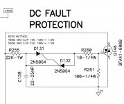
Workhorse said:How about using back to Back SCR's in Crowbar, yet another inexpensive solution....
The schematic that Workhorse posted seems interesting. Would this work on a +25 -25 volt supplied Gainclone?
@Workhorse
It's going back a bit, but could you explain how your back-to-back SCR arrangement works?
As I understand it, the idea with the Quad 405-style circuit is for a 2-wire Silicon Bilateral Switch to block the voltage across it until a set threshold is reached, whereupon the device turns on with low resistance and voltage across it, allowing the charge on the cap to trigger the main TRIAC - which needs a hefty pulse. Unfortunately here in the UK, my usual supplier, Farnell, has decided to sell all such devices with an extortionate 'U.S. stock surcharge' (do they realise how much of a rip-off this looks? Are U.S. customers also stung for 'UK stock' surcharges?) and I would therefore like to build the circuit using less exotic components if possible! Your circuit looks like just the job.
In your circuit, the SCR gate inputs are shown wired together and connected to nothing else, but I may be misinterpreting the diagram. What is it that triggers your circuit to conduct, and what is its threshold voltage?
Many thanks in advance.
Member
Joined 2009
Paid Member
Copper Top, I'd be happy to send you a couple of small parts by airmail from Canada if that helps get around the 'rip off britain' problem.
I'm going to be placing an order for parts from Digikey in the next few days and could include a couple of bits for you if they stock them at a price that makes sense to you: [http://www.digikey.com/ca/en/digihome.html]
PM me if interested.
I'm going to be placing an order for parts from Digikey in the next few days and could include a couple of bits for you if they stock them at a price that makes sense to you: [http://www.digikey.com/ca/en/digihome.html]
PM me if interested.
@Workhorse
It's going back a bit, but could you explain how your back-to-back SCR arrangement works?
As I understand it, the idea with the Quad 405-style circuit is for a 2-wire Silicon Bilateral Switch to block the voltage across it until a set threshold is reached, whereupon the device turns on with low resistance and voltage across it, allowing the charge on the cap to trigger the main TRIAC - which needs a hefty pulse. Unfortunately here in the UK, my usual supplier, Farnell, has decided to sell all such devices with an extortionate 'U.S. stock surcharge' (do they realise how much of a rip-off this looks? Are U.S. customers also stung for 'UK stock' surcharges?) and I would therefore like to build the circuit using less exotic components if possible! Your circuit looks like just the job.
In your circuit, the SCR gate inputs are shown wired together and connected to nothing else, but I may be misinterpreting the diagram. What is it that triggers your circuit to conduct, and what is its threshold voltage?
Many thanks in advance.
The back to back connected SCR's works in avalanche breakdown mode in that way and triggers the traic after a certain threshold in this case its 22V to 35V and Crowbar clamping is achieved.
Hope this helps🙂
Copper Top, I'd be happy to send you a couple of small parts by airmail from Canada if that helps get around the 'rip off britain' problem.
I'm going to be placing an order for parts from Digikey in the next few days and could include a couple of bits for you if they stock them at a price that makes sense to you: [http://www.digikey.com/ca/en/digihome.html]
PM me if interested.
Bigun
It's so kind of you to offer. There is one item which might be suitable. I would probably only need four of them. How would I pay you?
Digi-Key - 835-1126-1-ND (Manufacturer - BS08D-T112)
Many thanks.
- Home
- Amplifiers
- Solid State
- Protection Circuit - Crowbar - Zener vs SBS