U8 could be left away IMO (741s are not considered that sexy anymore nowadays - neiter are 748s).
The bias resistor should be the same as the DC resistance to ground that the inverzting input "sees". I.e. it should be about 1.5 and 1.8 k (difficult to determine exactly because of P2).
Regards
Charles
The bias resistor should be the same as the DC resistance to ground that the inverzting input "sees". I.e. it should be about 1.5 and 1.8 k (difficult to determine exactly because of P2).
Regards
Charles
Ok thanks Charles for your reply, I've removed U8.
Can I use a standard NE5532 (like U5 + U6) for U7? Since they are internally freq. compensated I won't need C25. (I know that there are better options for audio, but I have them in stock)
Wouldn't it be easier to power U7 from the same regulated +-15V PSU as U5 + U6 + Filters. Actually I can't find a reason why to power it from the Amp's powersupply, since I put everything on the same PCB.
durxter said:Svante,
Strange things happening here. I've been doing some simulations with WinISD and a spreadsheet from www.diysubwoofers.org they both say that the design I made should be right....
In the response graph below you see:
- Blue line: Fs 16,8 Hz
Qts 0,33
Vb 47 ltr
Portlength 35 cm, dia 4,7 cm
- Red line: Fs 20Hz
Qts 0,33
Vb 38,7 ltr
Port length 30cm, dia 4,7cm
- Green line: Fs 16,8 Hz
Qts 0,33
Vb 47 ltr
Portlength 35 cm, dia 10 cm
The only reason I can think of is that you didn't choose the same portdiameter (4,7 cm) as I did. When taking 10 cm I get the same response as in your graph with -3db of around 35Hz and a large peak. What pipe dimensions and enclosure volume did you use for the simulation?
I think I will go for your suggestion (red line). It looks better than my suggestion. I thought that a lower tuning gives better group delay, am I right?
About Basta;
I see that you can only pay by creditcard, which I don't have...are there other options?
But most of the changed parameters can be simulated with for example WinISD, except for the effect of Le, right?. Very nice software though.
Ah, silly me, I just found an error I did. Rather embarrasing, actually, my port length was 35 mm, not cm... Sorry about that.
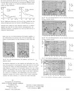
Anyway, here is how it looks when the port is tuned to 16.8 Hz (length 350 mm). It can be seen that the virtual parameters simulation matches your simulation very well, but that the full ACE simulation with Le results in a resonance at near 200 Hz. The resonance can be kept under control by a conjugate link.
I'll write you an email about the Basta questions.
An externally hosted image should be here but it was not working when we last tested it.
phase_accurate said:U8 could be left away IMO (741s are not considered that sexy anymore nowadays - neiter are 748s).
The bias resistor should be the same as the DC resistance to ground that the inverzting input "sees". I.e. it should be about 1.5 and 1.8 k (difficult to determine exactly because of P2).
Regards
Charles
Agree that U8 probably could be removed, but if so also R29 should be removed or C28 doubled. And yes, 741 and 748 should probably be replaced by a more modern OP amp, even though it will not matter much for these low frequencies.
Hi durxter
Did you ever build the circuit?
If so how did it work??
Did you calculate the rest of the components , Ccp, Rrp, Rrs, Rlp, Rg???
What values did you use?
I want to try our the Ace Bass concept. It's really a nice concept, and seems much better than LT.
I've build an LT with a 12" Peerless XLS driver and a 350 W power amp. It's good, but not really powerfull enough for HT use. It's not the most efficient way to use the driver. Using a bass port or a slave is far more efficient, and using Ace Bass seems to get the best of both worlds + reduction in distortion 😀
Please write about your experiences ..... or anyone else who have build something like this.
Best regards Baldin
Well with the Christmas holidays, you can't just sit and eat 😉
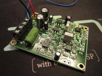
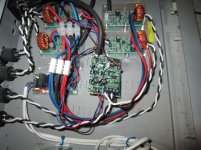
So I populated the PCB for my AceBass circuit whic has been in my drawer for some time.
.... and it actually works like a charm 😀
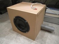
I used my small 6.5" Peerless woofer (which I use for my PC as sub) just for the initial trails:
Parameters before:
Cms = 1.0166
Mms = 18.5
Rms = 1.5239
Fs = 36.7
Qts = 0.59
Vas = 28.5
With AceBass:
Cms = 0,6
Mms = 80
Rms = 30
Fs = 23.0
Qts = 0.32
Vas = 16.8
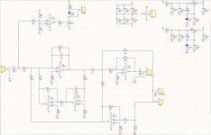
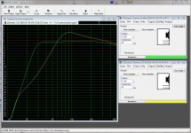
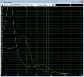
I have attached the schematic used, data in WinISD (AseBass in green) for transfer function and group dealy.
I have made a small Excel sheet for calculations which I'll upload to my blog if anyone are interested (600kb)
It's really fun to hear how deep this small speaker now goes 😉
So I populated the PCB for my AceBass circuit whic has been in my drawer for some time.
.... and it actually works like a charm 😀
I used my small 6.5" Peerless woofer (which I use for my PC as sub) just for the initial trails:
Parameters before:
Cms = 1.0166
Mms = 18.5
Rms = 1.5239
Fs = 36.7
Qts = 0.59
Vas = 28.5
With AceBass:
Cms = 0,6
Mms = 80
Rms = 30
Fs = 23.0
Qts = 0.32
Vas = 16.8
I have attached the schematic used, data in WinISD (AseBass in green) for transfer function and group dealy.
I have made a small Excel sheet for calculations which I'll upload to my blog if anyone are interested (600kb)
It's really fun to hear how deep this small speaker now goes 😉
Attachments
Here are a few pictures:
Read more on my blog, and download schematic and calculation sheet:
AceBass up and running | Baldin's Blog
I made a small PCB for the circuit, but it is easily made up on a bit of breadboard.
I would love to hear if someone fries it out .....
Best regards Baldin
Read more on my blog, and download schematic and calculation sheet:
AceBass up and running | Baldin's Blog
I made a small PCB for the circuit, but it is easily made up on a bit of breadboard.
I would love to hear if someone fries it out .....
Best regards Baldin
Attachments
Dear Baldin,
Would it be possible to post an cone excursion graph of your Peerless 6.5 "sub? Even better THD plots down to 25 Hz?
Kind regards,
Eelco
Would it be possible to post an cone excursion graph of your Peerless 6.5 "sub? Even better THD plots down to 25 Hz?
Kind regards,
Eelco
Aucosticraft ... Yes I use it together with class-d
Boden ... Simulations says I should reach Xmax at around 200 W input and get an SPL around 90 db .... but I'm not sure this is the truth .... I only feed it with around 25 W, so that should be something like 82 db at 25 Hz!!! .... but it sounds louder!!!
Anyway there is no way around physics ... so this is no SPl monster at all ... but it is quite good for use together with my PC speakers.
What AceBass can do is provide you with very deep bass, less distortion and make use of a vent to provide higher output than is possible with a sealed design.
Aucosticraft ... Yes I use it together with class-d
Boden ... Simulations says I should reach Xmax at around 200 W input and get an SPL around 90 db .... but I'm not sure this is the truth .... I only feed it with around 25 W, so that should be something like 82 db at 25 Hz!!! .... but it sounds louder!!!
Anyway there is no way around physics ... so this is no SPl monster at all ... but it is quite good for use together with my PC speakers.
What AceBass can do is provide you with very deep bass, less distortion and make use of a vent to provide higher output than is possible with a sealed design.
however the difference between the unassisted driver and the ace bass response is essentially the amount of additional power required from the amp which in this example appears to be about 6 dB @ 20Hz and 12 dB @ 30Hz and 7 db @ 40Hz so it's easy to see how you could run out of amplifier power.
Dear Baldin,
I am aware of the ACE claims of reducing distortion. I would certainly like to see this claim substantiated by measurement. I am in particular interested in a comparison between MFB and ACE techniques.
YT,
Eelco
I am aware of the ACE claims of reducing distortion. I would certainly like to see this claim substantiated by measurement. I am in particular interested in a comparison between MFB and ACE techniques.
YT,
Eelco
Attachments
Dear Baldin,
I am aware of the ACE claims of reducing distortion. I would certainly like to see this claim substantiated by measurement. I am in particular interested in a comparison between MFB and ACE techniques.
YT,
Eelco
MFB seems mostly dedicated to closed boxes as ACE can be used with bass-reflex. Using the same driver for both, you probably get better transient response from MFB, and lower distorsion from ACE.
ACE Bass is actually a kind of MFB.
The big advantage is that you can desig the Thiel-Small parameters to suit your purpose, and use it in a vented design.
As you can see from bjorno's attachment, there is definetly an improvement in distortion performance.
The big advantage is that you can desig the Thiel-Small parameters to suit your purpose, and use it in a vented design.
As you can see from bjorno's attachment, there is definetly an improvement in distortion performance.
Hi Baldin,
ACE Bass is actually a kind of MFB.
-->
ACE bass relies on complex feedback loops around a power amp, one of them providing a negative output resistance to nullify the DC resistance of the driver.
Is this MFB or not ? The inventor, Erik Stahl said "no" in his AES paper. But I would say like you : "kind of..."
Hi Baldin,
ACE Bass is actually a kind of MFB.
-->
ACE bass relies on complex feedback loops around a power amp, one of them providing a negative output resistance to nullify the DC resistance of the driver.
Is this MFB or not ? The inventor, Erik Stahl said "no" in his AES paper. But I would say like you : "kind of..."
ACE Bass is not MFB because there is nothing to sense the motion of the cone and no feedback loop with large loop gain.
I have no experience with Ace bass, but this made me curious.
could anyone tell me what results i could expect with a pair of JBL 2226J`s? in portet cabinets
Is the Ace bass prinsiple something that can be added to a regular amp, or would i have to tailor the amp to fit the job?
could anyone tell me what results i could expect with a pair of JBL 2226J`s? in portet cabinets
Is the Ace bass prinsiple something that can be added to a regular amp, or would i have to tailor the amp to fit the job?
I have no experience with Ace bass, but this made me curious.
could anyone tell me what results i could expect with a pair of JBL 2226J`s? in portet cabinets
Is the Ace bass prinsiple something that can be added to a regular amp, or would i have to tailor the amp to fit the job?
Hi,
The only requirement is that the amplifier is unity-gain-stable.
In my design I used a 47 pF compensation capacitor(Miller) to make the 748 Op-amp in use perform as an 741 type(inherent DC stable) + a small capacitor shunting the main feedback resistor.
If a positive gain type(normal) of main amp is used: a sign-inverter is needed, i.e. like a voltage follower in series preceding/connected (to (with)) the positive input of the main amplifier.
Power-amp closed loop gains above ~20 times is recommended.
Although I haven't tested 16 Ohms drivers: I wouldn't use the JBL 2226J drivers with ACE-bass due to the high Le, but certainty paralleled in a T-TQWT😀
b🙂
Last edited:
- Home
- Loudspeakers
- Subwoofers
- ACE-bass amplifier design