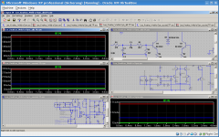
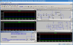
I use Eagle, Eagle 3D Povray.
Hi Federmann
I'm impressed! Looks stunning, not comparable at all.
My sreenshot was made with the basic 3D viewer. Mentor also offers a more advanced one but I bet this costs at least 4 digits.
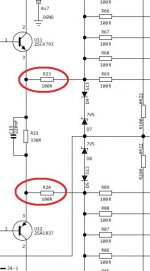
R23 and R24 are too large values
Thanks. 🙂 And most likely the gate stoppers R60-R69 and R80-R89 are too small. I better use the values from the latest AV1000. 10R for R23,R24 and 330R or 470R for R60-R69 and R80-R89.
Best Regards,
Lee
I still need to buy transistors for the input LTP cascode stage.
I'm not sure whether it's better to get the higher hfe ones for the cascode. Are higher hfe transistors better for the cascode stage?
Any ideas, please? 😕 🙂
Best Regards,
Lee
I'm not sure whether it's better to get the higher hfe ones for the cascode. Are higher hfe transistors better for the cascode stage?
Any ideas, please? 😕 🙂
Best Regards,
Lee
No, I haven't electrocuted myself yet. 🙂
It took a long time till I bought all necessary parts and matched the BJTs. I'm still waiting for tools and I'm not sure whether I can start assembly this weekend.
I spent my time with trolling around here annoying some users and thinking about this and that.
What still confused me was the Zener in the first LTP cascode reference and that you can use a BJT or a FET in the AV1000's Vgs/Vbe multiplier.
Now I found out that one can step temperature in LTspice and I further compared possible options in topology.
The way the Zener is connected in the Weld-a-Sym is copied from the *Sym amps that use a cascode in the input LTP. I actually didn't know what I'm doing there.
Another option is to connect the Zener to ground instead of the tail CCS.
And for curiousity I simulated the AV100 as well in a slightly modified version with the different input network and bias potentiometer just for my simulation convenience. I hope this doesn't affect the behavior too much but I don't think so.
For the two Weld-a-Sym amps I was able to equalize the LTP currents to 800uA for each leg and for all three amps I equalized the OP stage bias current to 90mA at standard temperature. After that a temperature step was simulated - 20, 30 and 60 °C. It is unlikely that all parts will experience the same temperature rise in reality but simulation still gives an idea what might happen.
The Weld-a-Sym is least sensitive to temperature change, the version with grounded Zener is more sensitive and the AV1000 is most sensitive.
The two current sources seem to compensate each other to some extent.
The AV1000 with BJT for temperature sensing might be seriously underbiased with temperature rise. But it also might be that the BJT compensates best if bias is set carefully. This should be tested in reality with an undersized heatsink since it looks promising.
I'm relieved that I wasn't totally wrong by luck. It would have annoyed me to find out the opposite.
Attachments
Tools arrived and I started assembly today.
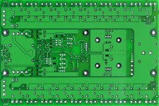
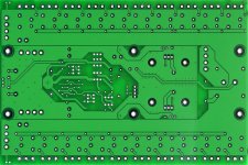
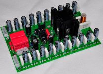
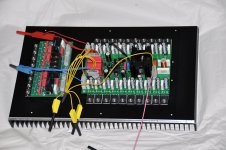
Here are some snapshots of the board without output stage FETs. The potentiometer and connection to Vgs multiplier are intentionally left out and I forgot the clamp diodes and LEDs.
Before I can continue, the pcb and components must dry. I cleaned the board immediately after assembly. This time flux was much easier to remove than with the rectifier boards where it had months to become really strong.
I'm glad I have no serious collisions with all the small heat sinks but the board will be very difficult to service.
Attachments
PCB
hi Lee,
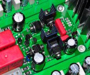
The board looks great, professional appearance!
Are you using low inductions MPC(75) source cement resistors?
regards,
Piersma
hi Lee,
The board looks great, professional appearance!
Are you using low inductions MPC(75) source cement resistors?
regards,
Piersma
Hi Piersma
Thanks. 🙂
PCB design is part of my profession.
I'm better at pcb design than at electronics design.
Yes, the source resistors are MPC74 from Futaba. They claim they are "low distortion factor products for acoustic products". They are said to be non-magnetic, too.
The power dissipated in the source resistors is very small but most designers use huge resistors there, so did I.
I've seen something very interesting in Anthony's latest designs: 2512 SMD resistors used as source resistors. They can handle 1W and there are also 2W versions available. What I expect from such a small resistor is that it will heat up with load and change their value a bit. First I thought 'What a silly idea. This must introduce some extra distortion.' But the resistors are still in NFB loop that will compensate this. The advantage of the small source resistors might be that they equalize current even better since they increase their resistance with temperature and give the FET doing most work more local NFB. Also, they may act as fuses in catastrophic failure cases.
Cheers,
Lee
PCB dried quickly and I tested the amp today.
With only one pair of FETs, cooled with the second pair of small heatsinks that are already on board, it seemed to work well.
For testing I used 40-0-40V smps current limited.
I didn't notice any change of bias (100mA) with temperature rise. The small heatsinks ran quite hot dissipating 4W.
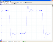
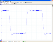
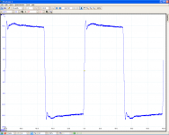
Response to square wave input looks reasonable to me. Just a tiny bit overshoot. There was no load connected since the FET already ran hot.
More worrying is what the output looks like with 100nF connected as load.
I think for further testing it makes sense to have the output stage complete, to use the huge heatsink and to connect a load. I can still use the current limited 40V supply and if everything works well test with the 90V supply.
With only one pair of FETs, cooled with the second pair of small heatsinks that are already on board, it seemed to work well.
For testing I used 40-0-40V smps current limited.
I didn't notice any change of bias (100mA) with temperature rise. The small heatsinks ran quite hot dissipating 4W.
Response to square wave input looks reasonable to me. Just a tiny bit overshoot. There was no load connected since the FET already ran hot.
More worrying is what the output looks like with 100nF connected as load.
I think for further testing it makes sense to have the output stage complete, to use the huge heatsink and to connect a load. I can still use the current limited 40V supply and if everything works well test with the 90V supply.
Attachments
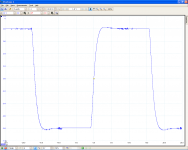
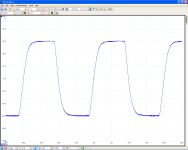
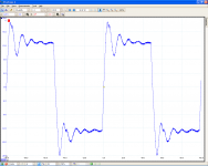

Ok, the amp survived the square waves.
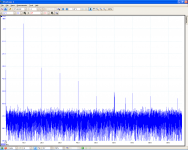
Let's see what the spectrum looks like. I have a lot of noise since my test setup was everything but clean (and the scope shows lots of noise anyway with shorted leads...) but spectrum still gives a hint how harmonics are distributed.
First one: 10kHz 32Vpp into 5R6 load.
Looks nice to me. 🙂
Dominant second harmonic, lower third, even lower fourth,... Interesting the 6th is higher than the 5th.
Attachments

From an engineer point of view , I must say that it looks really well an professionaly built!I completed the module and tested it today.
This is what it looks like at the moment:
A true solid German product.
My compliments!
effebi
Thanks, effebi. 🙂
What do you think about the waveforms? Do they look reasonable to you?
I'm not an experienced amp designer and not always sure how to interpret my measurements...
What do you think about the waveforms? Do they look reasonable to you?
I'm not an experienced amp designer and not always sure how to interpret my measurements...
- Status
- Not open for further replies.
- Home
- Amplifiers
- Solid State
- another one to build an AV800 / AV1000