Generally speaking, the smaller (your system can support), the better. Salas is absolutely right. Check the input impedance of the following component and calculate the right value for 10 - 15 Hz.
As we are dealing with a less than perfect source, even if you cut a bit of low frequencies, is not that bad. Think about all the problem related to the warp of records and/or plinth resonance.
I am preparing a salas riaa for a friend that uses seriously undamped speakers and in my first approach we noticed that the bass cones move wildly when there is not music playing (when the needle is on the cueing part of the disc).
My initial build has 6,8uF on the output and I guess even 4,7u is too much.
Following massimo´s idea I should xcalculate a -3dB rolloff at 10-15Hz.
Pelase inform if my calculations are right:
using the following formulae: C = 159155 / (R x F)
"The 'magic number' 159155 is derived from 1000000 / (2 * pi)"
Amp input impedance = 20k ohm
Rolloff freq = 10Hz
Cout should be 0.8uF
Riaa stage with subsonic filter.... embedded! Cute.
Only DIY can taylor a component to the system needs.
P.S. you should calculate Salas o/p imp//following amp i/p imp in your formula
Only DIY can taylor a component to the system needs.
P.S. you should calculate Salas o/p imp//following amp i/p imp in your formula
P.S. you should calculate Salas o/p imp//following amp i/p imp in your formula
Please explain in common language

Output impedance is only around 30 Ohm, will not change something much.
Just for learning purposes.... can you post the correct formulae ?
Merry Christmas!!!!!
I like this time of year as I get a little down time from work and can focus. Starting to complete a few of the project lists I have for the simplistic.
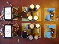
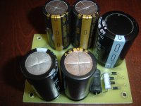
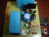
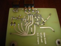
Attached are photo's of the new power supply and V1.2R for my simplistic. After a brief break to play with some of my kids gifts, I am going to breadboard it and fire it up.
I like this time of year as I get a little down time from work and can focus. Starting to complete a few of the project lists I have for the simplistic.
Attached are photo's of the new power supply and V1.2R for my simplistic. After a brief break to play with some of my kids gifts, I am going to breadboard it and fire it up.
Attachments
There is nothing more than the known first order CR high pass filter formula. Its if there is significant output impedance it forms a time constant with the capacitor that makes it appear bigger. In this case there is a buffer and the effect is negligible.
Calc.
My friend´s amp has an input impedance of 47kohm.... that alied to my 6,8uF output caps might be the cause to the weird woofer travel.
Must reduce the output cap value.
I like this time of year as I get a little down time from work and can focus. Starting to complete a few of the project lists I have for the simplistic.
Attached are photo's of the new power supply and V1.2R for my simplistic. After a brief break to play with some of my kids gifts, I am going to breadboard it and fire it up.
Congratulations on your HQ build.... Let us know your impressions 🙂
My friend´s amp has an input impedance of 47kohm.... that alied to my 6,8uF output caps might be the cause to the weird woofer travel.
Must reduce the output cap value.
The disc rumble around 6Hz due to eccentricity is the cause and the under damped vented speakers are exaggerating it, you just let it pass to be exact. Turning the phase early is not nice, but having such side effects its even worse. They create non useful allocation of much power among other things. Just cut as you have to given a system. Subsonic filters are not something odd in TT replay practice.
Please explain what do you mean by turning the phase early.
I know that we are wasting precious power just moving the woofer without producing any sounds but I know little about phase issues.
I know that we are wasting precious power just moving the woofer without producing any sounds but I know little about phase issues.
RCruz,
Salas will do a much better job at explaining, but "turning the phase" is a term meaning that the current becomes out of phase with the voltage. A perfect resistor would be in phase or at zero degrees. The principle of a filter is that it will shift the phase and as a result attenuate the signal at those frequencies. I believe that 45 degrees out of phase is the f3. (maybe 90, can't remember and my ref book is in other room buried.). Caps leads the phase shift and Inductors Lag the phase shift. At the time I was first taking math, I had no idea why I needed to know about imaginary numbers, now I wish I paid more attention as this is a perfect example of their application.
In regards to the PS. Thanks. I have installed and commisioned the dual mono xfmr and filters. Had a little trouble with the V1.2R as a result of confusion in my drawing. Parts are so close that the part description over lapped each other and I had Q7 and Q8 swapped. I doesn't appear that I let the magic smoke out of anything so I'll try again tomorrow. In the meantime I had the opportunity to listen to the improved power supply and filter with the original V1.2.
The sound is much more forward with the top end clarity improving. Imaging improved as well. In particular, images outside the speakers have a little more spook to them as they are very vivid and demand attention. Listening to RUSH tonight was like being on stage with them. Outside of the clarity on top, the rest of the tonal balance remains very similar to my notes prior to the change.
P.S. If you note, the air core inductor is gone and replaced with two 1.5mH chokes. The first one is part of a hash filter and the second one is part of the CLC filter. The measured ripple under load is 700uV going into the V1.2
Last edited:
Off to a good start with the new additions then. Don't forget the good primary to secondary isolation of the R-Cores to factor in positively also. What is your now cart loading value by the way?
Holding at 220R, May have to play again there.
The second R-core certainly changed things. Was barely able to hold 48V into the V1.2 before I broke the channels apart and added a second one. Now it is 53V solid.
The second R-core certainly changed things. Was barely able to hold 48V into the V1.2 before I broke the channels apart and added a second one. Now it is 53V solid.
There is nothing more than the known first order CR high pass filter formula. Its if there is significant output impedance it forms a time constant with the capacitor that makes it appear bigger. In this case there is a buffer and the effect is negligible.
Calc.
Using the calc. for an input impedance of 10K 1uF cutoff/corner frecuency 15.92Hz time constant 9.997us & 1.5uF cutoff/corner frecuency 10.61Hz time constant 15.000us, are my calculations right? what about the phase it's right?
I like this time of year as I get a little down time from work and can focus. Starting to complete a few of the project lists I have for the simplistic.
Attached are photo's of the new power supply and V1.2R for my simplistic. After a brief break to play with some of my kids gifts, I am going to breadboard it and fire it up.
Nice photos, where did you buy the Tx?
Holding at 220R, May have to play again there.
The second R-core certainly changed things. Was barely able to hold 48V into the V1.2 before I broke the channels apart and added a second one. Now it is 53V solid.
Where did you get those from? The ones I have used (French vendor, Indian make) hold very firmly. But that is not a big concern, can be specified for more voltage after having tested one and knowing how much it sags. The main thing is to be aligned correctly in manufacture though. So to cancel stray field as they should and allow single box constructions. If the mains inlet is shielded and the primary wires are dressed well and away from inputs, also.
- Home
- Source & Line
- Analogue Source
- Simplistic NJFET RIAA