Hi
Any experts who can help me design a TL?
I intend to use 4 Focal 7K415 bass/midrange drivers I have laying around. I will use an Tangband 4W 1320 bamboo fullrange for the midrange/tweeter. I am not sure about the crossover frequency between these two drivers yet.
I was thinking of placing a Focal on the front and one on the back of the loudspeaker. Each having its own TL enclosure, but only the front will play into the midrange.
I know the Focals are not a classical driver for a TL but I would still like to try. If it does not work it will only cost me the materials for the cabinet.
Dimension for the cabinet. I would like to keep it under 12" ( 30 cm ) wide and under 20" ( 50 cm ) deep. hight is not an issue.
Specs of 7K415:
Fs 32,5 hz
Vas 56 liter
Qts .26
Qes .29
Qms .2,52
Rcc 7,8 ohm
Sd 163 cm2
Mms 16 gramRms 1,3 kg/s
Any ideas?
best regards
Uwe
Download Martin King's alignment tables (and spreadsheet) and start there.
Transmission Line Theory
dave
Transmission Line Theory
dave
..I was thinking of placing a Focal on the front and one on the back of the loudspeaker. Each having its own TL enclosure, but only the front will play into the midrange..hight is not an issue..Any ideas?..
Hi, here is one idea:
b 🙂
Attachments
Hi Bjorno
Thank u for the reply.
I am not used to read the results from Hornrespons.
But as i see it you suggest that:
Front enclosure is a basreflex cabinet where inside length is so long that it acts as a TL and this is transferred to the room via a normal basreflex port.
Back enclosure is more like a standard TL.
But the way you positioned the drivers they will not eliminate there mechanical forces on the cabinet. Can I turn the rear enclosure upside down so that the driver is on top?
How deep is the combined enclosure?
Have you heard of the fuzzy technologie that they use for TL and also for horns in the magazine Hobby HiFi from Germany?
Best regards
Uwe
I built a TL, based on Dr Bailey's revised design.
The beauty of the TL is that the rear sound is ultilised.
However there are to many variables to deal with ie line length and cavity/or not (which you cant change after building) stuffing material and the amount ( keeping it in place and the ease/problem of altering it in built box) port size etc...
During 8 years of messing i did briefly get a good sound, but do you want to be messing so long, i looked into m.kings info but basically it does not really model a TL to the point where your say 85% done before you cut wood.
I have since moved to closed box designs, these are highly predicatable to model and with the addition of a LTX cct, can offer true bass to whatever frequency you choose.
If you couldn't use Martin's worksheets to end up with a TL design that needed little or no fiddling with after it was built, then clearly either you didn't learn/understand well enough how to use them, or you have some rather unusual requirements or hearing. I've modeled dozens and dozens of TLs for personal and for others' use, and built 7 designs for personal use, all modeled with Martin's worksheets. Assuming a driver will work well in a TL, I can arrive at an acceptable TL model in literally minutes, and can optimize it in a few hours at most (and it's way more than 85% done). I've never had to tweak anything about a TL after it was built (crossovers excluded). You won't find anything more accurate than Martin's work IMO.
Paul
Paul
I built a TL, based on Dr Bailey's revised design.
The beauty of the TL is that the rear sound is ultilised.
However there are to many variables to deal with ie line length and cavity/or not (which you cant change after building) stuffing material and the amount ( keeping it in place and the ease/problem of altering it in built box) port size etc...
During 8 years of messing i did briefly get a good sound, but do you want to be messing so long, i looked into m.kings info but basically it does not really model a TL to the point where your say 85% done before you cut wood.
I have since moved to closed box designs, these are highly predicatable to model and with the addition of a LTX cct, can offer true bass to whatever frequency you choose.
hi
I would like to make a closed box but with only 2 7" woofers pr side it will not play loud or deep enough.
If I have to go for a closed box no less than two 10" will do.
Uwe
I would like to make a closed box but with only 2 7" woofers pr side it will not play loud or deep enough.
If I have to go for a closed box no less than two 10" will do.
Uwe
I got inspiration from Pkitt's advice on how to use a Seas Aluminium 10" in a tapered TL ,advice given to someone else , and I built something like that...and it works . But Heinz64 worries about mechanical-vibration in the enclosure and he's right ,those forces couple and transfer rapidly to midrange's basket ,so it might be an issue . Instead of putting a new ext suspension to my 10" ,I've also considered the use of two 7-8" one aside the other (up & down 😉) but it's hardly predictable of how they would interfere each other ,sharing the same acoustic load . BTW All speakers and cabinets put in their equation the backwave 
Cool !! The Yin and the Yang.
Again ?
Cool !! The Yin and the Yang.
Again ?
If you couldn't use Martin's worksheets to end up with a TL design that needed little or no fiddling with after it was built, then clearly either you didn't learn/understand well enough how to use them, or you have some rather unusual requirements or hearing. I've modeled dozens and dozens of TLs for personal and for others' use, and built 7 designs for personal use, all modeled with Martin's worksheets. Assuming a driver will work well in a TL, I can arrive at an acceptable TL model in literally minutes, and can optimize it in a few hours at most (and it's way more than 85% done). I've never had to tweak anything about a TL after it was built (crossovers excluded). You won't find anything more accurate than Martin's work IMO.
Paul
1. I actually conversed with king on the use/application of his worksheet
2. Just because youve built anything does not make you an authority (most people who knock anything up are so pleased it works at all)
3. Quote "assuming the driver will work"???
4. OK so youve optimised it, so it looks good on the screen, did you verify it with acoustic tests or just apply point #2 ???
5 Yes you wont find anything more accurate, but is it accurate at all???
At least you didnt argue with my point on sealed boxes.......
I'd be more interested in the 'fuzzy' variations that can be proposed .
TL in respect to PS is far slower , as the air mass is very lazy ,since the time delay from when the attack happens and the fundamental exits from the line terminus ,depends from it ,as also from geometry (bends) and how and where some resistance is applied (fluffy 🙄). Transients made and measured with a PS are naturally the best among all the acoustic loads.
.....
I would put those Focals in a TQWT ...I like much all the 'fuzzy' things .
Maybe a divider between the two drivers in the first part of the line ,terminus being about 10 cm2 and lamellar !!!
1. Apparently your conversation with Martin didn't result in you being able to have confidence in his worksheets being accurate enough to suit you.
2. I've never claimed to be an expert or authority on TLs, but I have modeled many, many TLs, some for personal use and many more for others. In fact, if you go to the Salk Sound website, you'll see he commercially distributes 5 speaker systems for which I designed their ML-TL cabinets.
3. Due to their specific characteristics, some drivers work well in sealed boxes but not vented boxes, and vice versa, while some drivers will work well in either. It's no different when it comes to TLs. Some drivers will work well in an ML-TL, an ML-TQWT or a tapered TL but not all. Some drivers will work well in almost any kind of TL. And, some drivers don't work well in a TL at all.
4. After building my first couple TL designs that were modeled with Martin's worksheets, I performed extensive electrical and acoustical tests/measurements to confirm their actual performance was equal to or very close to their predicted performance. They were and I no longer have any need for further confirmation.
5. My answer to number 4 verifies Martin's worksheets give accurate results, plus TL-modeling software from others, like George Augsperger, attain virtually identical results.
Paul
1. I actually conversed with king on the use/application of his worksheet
2. Just because youve built anything does not make you an authority (most people who knock anything up are so pleased it works at all)
3. Quote "assuming the driver will work"???
4. OK so youve optimised it, so it looks good on the screen, did you verify it with acoustic tests or just apply point #2 ???
5 Yes you wont find anything more accurate, but is it accurate at all???
At least you didnt argue with my point on sealed boxes.......
Hi
Any experts who can help me design a TL?
We will see.....
Last edited:
I'm no expert but I'm willing to help; however, I will need the value for Le. Actually I also need the value for BL but I will be able derive Bl from all of the other T/S values you posted. That said, drivers with low Qts are almost always more difficult to get to work well in a TL, IMO, and they tend to work best in an ML-TQWT. Since you hope to have one 7K415 on the front and another on the back, with the back one only providing bass response, I can envision the one on the baffle mounted near the top below the TB driver, and the one on the rear mounted near the bottom. This would allow a single angled divider to form the ML-TQWT cavities for both Focals.
Paul
Paul
Hi
Any experts who can help me design a TL?
I intend to use 4 Focal 7K415 bass/midrange drivers I have laying around. I will use an Tangband 4W 1320 bamboo fullrange for the midrange/tweeter. I am not sure about the crossover frequency between these two drivers yet.
I was thinking of placing a Focal on the front and one on the back of the loudspeaker. Each having its own TL enclosure, but only the front will play into the midrange.
I know the Focals are not a classical driver for a TL but I would still like to try. If it does not work it will only cost me the materials for the cabinet.
Dimension for the cabinet. I would like to keep it under 12" ( 30 cm ) wide and under 20" ( 50 cm ) deep. hight is not an issue.
Specs of 7K415:
Fs 32,5 hz
Vas 56 liter
Qts .26
Qes .29
Qms .2,52
Rcc 7,8 ohm
Sd 163 cm2
Mms 16 gramRms 1,3 kg/s
Any ideas?
best regards
Uwe
A possibility (ML-TL)
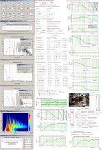
Okay, I came up with something for you to consider. It's an ML-TL that I modeled for ONE driver. The cabinet could be separated in the middle of its depth by a solid divider. The internal dimensions for one line would be 8.5"W x 6"D x 38"H. For the front line, the center of the 7k415 would be located 8" below the inside of the top of the ML-TL enclosure. The center of the mass-loading port would be located 3" above the inside of the bottom, with the port having a diameter of 2.5" and a length of 3.75". The stuffing density would be 0.5 lb/ft3, requiring a total of 5.5 to 6 ounces of polyester-type fill in the top 24" of this line enclosure. For the back, identical line, since that 7k415 would be only for bass, you could turn the line upside down with the driver close to the floor if you wanted, or you could orient it exactly the same as the front line. Since the TB midrange/tweeter will need a separate cavity, that could be created and placed on top of the two line enclosures, separated by a solid divider. If the solid divider that separates the two lines is 3/4" thick, then the total internal depth would end up at 12.75". If a 6" height above the two lines and their divider allows adequate volume for the TB driver, total internal height would end up at ~46". I've attached a graph of the modeled response of the TL. Others may be able to come up with something better.
Paul
Hi
Any experts who can help me design a TL?
I intend to use 4 Focal 7K415 bass/midrange drivers I have laying around. I will use an Tangband 4W 1320 bamboo fullrange for the midrange/tweeter. I am not sure about the crossover frequency between these two drivers yet.
I was thinking of placing a Focal on the front and one on the back of the loudspeaker. Each having its own TL enclosure, but only the front will play into the midrange.
I know the Focals are not a classical driver for a TL but I would still like to try. If it does not work it will only cost me the materials for the cabinet.
Dimension for the cabinet. I would like to keep it under 12" ( 30 cm ) wide and under 20" ( 50 cm ) deep. hight is not an issue.
Specs of 7K415:
Fs 32,5 hz
Vas 56 liter
Qts .26
Qes .29
Qms .2,52
Rcc 7,8 ohm
Sd 163 cm2
Mms 16 gramRms 1,3 kg/s
Any ideas?
best regards
Uwe
Attachments
to the OP:
MJKs worksheets are very good, I do not have them personally, i used the alignment tables and a calculator! However, If you just want to do a quick 'sketch' design, for just an experiment, then i recommend you try this quick spreadsheet calculator:
http://www.quarter-wave.com/TLs/Alignment_Tables_Calculator_3_3_09.xls
the likes of pkitt are very helpful with regard to TL sims, and providing response graphs, which the Excel sheet doent do, but dont be afraid to experiment.
I, Myself have had much help from others, but with the greatest of respect to all of them, i preferred to find a method of my own, using the excel sheet.
the Author of said sheet, mentions altering the tuning frequency slightly depending on driver Qts.
I had a (somewhat crazy, or maybe inspired) idea, to simply use the Vb/Vas to Qts curves from from Thiele & Small vented design to adjust the tuning frequency, where Vb=Vas=1=F3 factor when driver Qts~0.38
for this driver qts=0.38 i would tune to Fs, higher or lower Qts i would trace the curve to find the F3 factor and apply that to the pipe tuning.
eg for a qts=0.5 would give Vb/Vas of 2, which in turn would give me an F3 factor of about 0.7 times the Fs, which would be the tuning frequency. Looking at your driver, with qts ~0.3, i get about 1.5 times the Fs, or about 48Hz, as the QW tuning. this is the number i would plug into the sheet i linked.
(disclaimer: someone may sim this in MJKS sheets and tell me im way off, so dont just take my word for it. 😀
probaby nothing new at all, its just the way i found to keep TL design simpler for me, and less time simming(or rather asking others to sim for me). MJKs work is brilliant, but im English and i hate paying for anything if i can figure out my own path 😉
Last edited:
If you want a pretty smooth/flat overall response from the knee in the curve on up, then choosing the optimum overall tuning frequency is critical, and that depends quite heavily on the driver's Qts and Fs. According to the specs for this Focal 7k415 driver that the OP listed, Fs is 32.5 Hz and Qts is 0.26. Those two facts indicate an optimum tuning more than a little bit higher than Fs would be needed. The model I posted had an overall tuning frequency at ~41 Hz. A tuning frequency of 48 Hz for this driver, however, would be unnecessarily high, IMO, likely causing the low end response from 100 Hz down to the knee in the curve to be tilted up, ending up with possibly an unnaturally heavy bass sound (some may like it that way, of course). That's the problem with not being able to model what you design; you can't see the likely response.
In case anyone is interested, the response graph I posted was for an input of 2.83 volts, and I arbitrarily modeled with 0.5 ohms added in series with the driver. I also modeled with Le=zero since that value was not listed.
Paul
In case anyone is interested, the response graph I posted was for an input of 2.83 volts, and I arbitrarily modeled with 0.5 ohms added in series with the driver. I also modeled with Le=zero since that value was not listed.
Paul
to the OP:
MJKs worksheets are very good, I do not have them personally, i used the alignment tables and a calculator! However, If you just want to do a quick 'sketch' design, for just an experiment, then i recommend you try this quick spreadsheet calculator:
http://www.quarter-wave.com/TLs/Alignment_Tables_Calculator_3_3_09.xls
the likes of pkitt are very helpful with regard to TL sims, and providing response graphs, which the Excel sheet doent do, but dont be afraid to experiment.
I, Myself have had much help from others, but with the greatest of respect to all of them, i preferred to find a method of my own, using the excel sheet.
the Author of said sheet, mentions altering the tuning frequency slightly depending on driver Qts.
I had a (somewhat crazy, or maybe inspired) idea, to simply use the Vb/Vas to Qts curves from from Thiele & Small vented design to adjust the tuning frequency, where Vb=Vas=1=F3 factor when driver Qts~0.38
for this driver qts=0.38 i would tune to Fs, higher or lower Qts i would trace the curve to find the F3 factor and apply that to the pipe tuning.
eg for a qts=0.5 would give Vb/Vas of 2, which in turn would give me an F3 factor of about 0.7 times the Fs, which would be the tuning frequency. Looking at your driver, with qts ~0.3, i get about 1.5 times the Fs, or about 48Hz, as the QW tuning. this is the number i would plug into the sheet i linked.
(disclaimer: someone may sim this in MJKS sheets and tell me im way off, so dont just take my word for it. 😀
probaby nothing new at all, its just the way i found to keep TL design simpler for me, and less time simming(or rather asking others to sim for me). MJKs work is brilliant, but im English and i hate paying for anything if i can figure out my own path 😉
If you want a pretty smooth/flat overall response from the knee in the curve on up, then choosing the optimum overall tuning frequency is critical, and that depends quite heavily on the driver's Qts and Fs. According to the specs for this Focal 7k415 driver that the OP listed, Fs is 32.5 Hz and Qts is 0.26. Those two facts indicate an optimum tuning more than a little bit higher than Fs would be needed. The model I posted had an overall tuning frequency at ~41 Hz. A tuning frequency of 48 Hz for this driver, however, would be unnecessarily high, IMO, likely causing the low end response from 100 Hz down to the knee in the curve to be tilted up, ending up with possibly an unnaturally heavy bass sound (some may like it that way, of course). That's the problem with not being able to model what you design; you can't see the likely response.
In case anyone is interested, the response graph I posted was for an input of 2.83 volts, and I arbitrarily modeled with 0.5 ohms added in series with the driver. I also modeled with Le=zero since that value was not listed.
Paul
Was that response from MJKs sheets?
What I've read so far would suggest that a Qts of .26 is too low? And would result in a tuning freq of about 136 Hz. (Maybe I need to hone my methods so far, or read something else?) But I have no idea how that would model or what the roll off would be.
I do like the look of your response though
Yes, I modeled this with Martin's worksheet and posted the resulting system bass response. IME, drivers having a low Qts are always more difficult to work with for a TL, but there's more to it than just Qts, so sometimes reasonably good results do occur. I don't know how you arrived at a tuning frequency of 136 Hz. In a non-folded ML-TL like this, the internal height of the cabinet is the line's length and that length's 1/4-wavelength resonant frequency provides some of the overall system tuning, with the rest of the tuning provided by the mass-loading port's dimensions. In a more conventional line that is longer or longer and tapered, the line's length, as affected by its taper, if any, contributes all of the system tuning. In an ML-TL, being able to model the exact location of the port relative to the driver and line length allows one to maximize smoothness, too. The overall system tuning frequency primarily determines the overall response shape, and the volume contained within the line primarily determines how low F3 ends up.
Paul
Paul
Was that response from MJKs sheets?
What I've read so far would suggest that a Qts of .26 is too low? And would result in a tuning freq of about 136 Hz. (Maybe I need to hone my methods so far, or read something else?) But I have no idea how that would model or what the roll off would be.
I do like the look of your response though
- Status
- Not open for further replies.
- Home
- Loudspeakers
- Multi-Way
- Need help for TL design