hi
thank u for this sir.
hello sirHi,
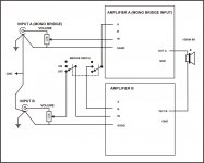
if you have a balanced source fed in through an XLR plugged cable then you don't need a bridged switch. Each half of the amplifier will be driven by the hot or cold input pins.
Read Rane, Jensen, D.Self, ESP.
thank u for this sir.
hello everyone pls help me for XLR input with stereo bridge switch
This is simple XLR input circuit.
I suggest to use 2 way x-over with XLR input, and 3 position switch to select input mode (subwoofer, satelite or full range)
Regards
Attachments

if the clip LED illuminates on a very fast transient, can it be seen?
How long does the transient have to last for our eyes to see the light?
Do we need a timer to hold the LED on for maybe 1ms?
Clip LED light 10V before amp clip, that give visualable time light.
How do you know whether a 1us clip or a 100us clip or a 10ms clip gives a visual warning?Clip LED light 10V before amp clip, that give visualable time light.
I don't know.
Maybe a prolonged series of 100us clips are visible, again I don't know.
I suspect some form of peak hold is required to show fast transient clipping. I seriously doubt that short clips will be visible without a peak hold facility.
For comparison purposes, a half wave of 20kHz is only 25us duration.
If only the top half of that half sinewave triggers the LED into conduction, then that gives rise to a 12us clip indication. Can we see that?
miles help me with this when using 12 o/p pair wat should be the driver transistor be MJE15033/32
or should I use the O/P transistor as driver ........ plz reply soon
regards
sekhar
or should I use the O/P transistor as driver ........ plz reply soon
regards
sekhar
reactive impedance filters back through the stages.
If a 12device output stage is required to provide sufficient SOAR then the driver/s must also be designed to survive that reactive loading.
1pr of cold To220 are unlikely to have adequate SOAR to drive that many hot outputs.
If a 12device output stage is required to provide sufficient SOAR then the driver/s must also be designed to survive that reactive loading.
1pr of cold To220 are unlikely to have adequate SOAR to drive that many hot outputs.
miles help me with this when using 12 o/p pair wat should be the driver transistor be MJE15033/32
or should I use the O/P transistor as driver ........ plz reply soon
regards
sekhar
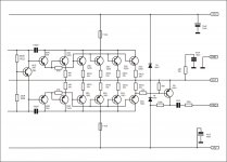
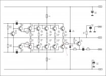
Use this output stage for more o/p pairs,
Regards
Attachments

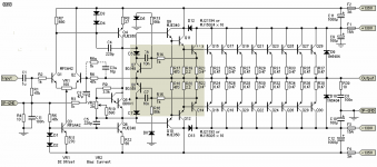
the V part of VI limiting has been omitted.
You need to check a working VI circuit and then modify the component values to suit your amplifier.
You need to check a working VI circuit and then modify the component values to suit your amplifier.
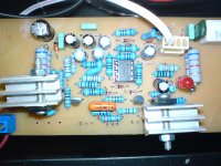
can i add the vi limiter in b500 shown in the picture................
regards
sekhar
Use this MACKIE schematic for VI limiter (value for 2SA1943/2SC5200)
Regards
Attachments
i am falling asleep ..................................😴😴😴😴😴😴😴
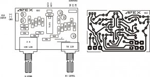
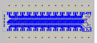
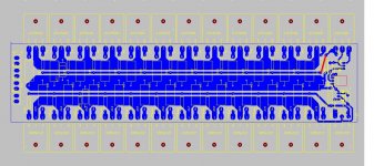
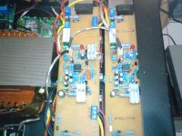
here is a sneak peek of the updated pcb still a lot of work to do will update tomorrow ....................and pcb size finalized 300mm X 68 mm..... max can be a bit less......
regards
sekhar
here is a sneak peek of the updated pcb still a lot of work to do will update tomorrow ....................and pcb size finalized 300mm X 68 mm..... max can be a bit less......
regards
sekhar
Attachments
sekhari am falling asleep ..................................😴😴😴😴😴😴😴
here is a sneak peek of the updated pcb still a lot of work to do will update tomorrow ....................and pcb size finalized 300mm X 68 mm..... max can be a bit less......
regards
sekhar
wake up buddy
time to work
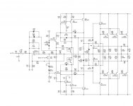
hi apexaudio
greetings should R23 BE 680 OHMS or is 330 OHMS correct will
MJE340 MJE NEED heatsinks
thanking you
andrew lebon
greetings should R23 BE 680 OHMS or is 330 OHMS correct will
MJE340 MJE NEED heatsinks
thanking you
andrew lebon
i am falling asleep ..................................😴😴😴😴😴😴😴
here is a sneak peek of the updated pcb still a lot of work to do will update tomorrow ....................and pcb size finalized 300mm X 68 mm..... max can be a bit less......
regards
sekhar
Track mising
Attachments
hi apexaudio
greetings should R23 BE 680 OHMS or is 330 OHMS correct will
MJE340 MJE NEED heatsinks
thanking you
andrew lebon
For BIAS setup R22 should be 1k2 instead 680R for triple darlington output stage, and R23 is correct 330 ohms.
Q5 (MJE340) must be on main heatsink with outputs.
Predrivers MJE340/350 can use smal heatsinks, but no need.
Regards
Hi Mr. Mile
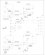
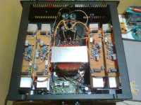
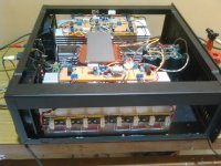
i have built B500 in bridge mode, i use 1800va transformer ,rail voltage 63+/- vdc(45ct45) . caps 6 x 10.000/100vdc. are those caps enaugh for this ?
i have built B500 in bridge mode, i use 1800va transformer ,rail voltage 63+/- vdc(45ct45) . caps 6 x 10.000/100vdc. are those caps enaugh for this ?
Attachments
Stringent SOA needs in Class-AB are met with relaxed ones in Class-H.
For example, 1kW @ 2Ohms in Class-AB using 5200/1943 requires atleast 9-10Pairs with rails around +/-90V whereas only 5Pairs will do the job in Class-H if rails are split in say +/-55 & +/-95.
In a Class- AB reactive loading we have high dissipation because output device has considerable VCE + Ic across it hence heating very much, Whereas in Class-H, this VCE is quite less across the device for same output load, hence less heat and more headroom.
- Home
- Amplifiers
- Solid State
- 500W PA amplifier with Limiter