Recently I had a discussion in the Chip Amp section with some of you about whether or not to connect safety earth or protective earth (I'll call it PE from now on) to the chassis of DIY equipment (http://www.diyaudio.com/forums/chip-amps/176410-odd-grounding-problem.html). This had me going over all the wiring of my audio and video equipment. At a certain point I was reconnecting the SPDIF coax from my unearthed (appliance class II) CD-player to my earthed (aplliance class I) DAC. Because I had to reach behind the two I happened to grab the outside of the RCA connector attached to the CD-player while I touched the DAC's chassis with my wrist. That felt like being bitten or something.
I measured the AC voltage with a DMM (10 M input impedance) between the chassis of both devices.
There was a 200 Vac differential between them with the CDP switched off that dropped to about 100 Vac when switched on.
I reversed the mains plug of the CDP and got less then 2 Vac when switched off, but still about 100 Vac when switched on.
Now this CDP has been giving me a lot of aggro over the years which I thought to have solved a while ago (http://www.diyaudio.com/forums/digital-source/133909-very-strange-fault-cd-player.html). Not so long ago it began to misbehave again, so I gave up and connected the SPDIF to the DAC (it's the analogue stage that keeps going wrong).
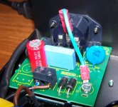
But after being bitten, I inspected the innards of the CDP again, but now focusing on the filter behind the mains entrance. Despite having a 3-prong IEC socket, the PE has deliberately not been connected by the manufacturer, thus selling it as a class II device. The design of the mains filter, though, looks like it had originally been designed for a class I device. Perhaps in a more expensive guise, this CDP would have had balanced connections. Usually PE is connected to the chassis when balanced in- and outputs are used.
Closer inspection after removal of the filter pcb confirmed my suspicion that C2 and C3 are across L and PE and N and PE (or rather would-be-PE). As you can also see in the picture the PE pin has been cut before insertion in the pcb.
Under the screw, marked G1, is a copper threaded standoff fixed to the chassis. It touches a pad that would have connected to PE of the mains entrance. I'm assuming the high potential between my DAC and the CDP is caused by C2 and C3 as long as it's connected to mains but not yet to the DAC.
While unscrewing G1 I noticed it wasn't very tight, so the connection to the chassis might not have been very good, perhaps intermittent. Recently I noticed the display of the CDP scrambling whenever I switched the DAC on or off. Might this have something to do with the not-so-good connection of the filter pcb to the chassis?
Isn't it a bit strange that a mains filter clearly designed to be used with PE can find its way into a class II appliance?
Wouldn't that mean high leakage current trough the interlink shields to the DAC?
But my main question is: can I (or rather, am I allowed to) connect PE to the chassis changing it into a class I device?
I measured the AC voltage with a DMM (10 M input impedance) between the chassis of both devices.
There was a 200 Vac differential between them with the CDP switched off that dropped to about 100 Vac when switched on.
I reversed the mains plug of the CDP and got less then 2 Vac when switched off, but still about 100 Vac when switched on.
Now this CDP has been giving me a lot of aggro over the years which I thought to have solved a while ago (http://www.diyaudio.com/forums/digital-source/133909-very-strange-fault-cd-player.html). Not so long ago it began to misbehave again, so I gave up and connected the SPDIF to the DAC (it's the analogue stage that keeps going wrong).
But after being bitten, I inspected the innards of the CDP again, but now focusing on the filter behind the mains entrance. Despite having a 3-prong IEC socket, the PE has deliberately not been connected by the manufacturer, thus selling it as a class II device. The design of the mains filter, though, looks like it had originally been designed for a class I device. Perhaps in a more expensive guise, this CDP would have had balanced connections. Usually PE is connected to the chassis when balanced in- and outputs are used.
Closer inspection after removal of the filter pcb confirmed my suspicion that C2 and C3 are across L and PE and N and PE (or rather would-be-PE). As you can also see in the picture the PE pin has been cut before insertion in the pcb.
Under the screw, marked G1, is a copper threaded standoff fixed to the chassis. It touches a pad that would have connected to PE of the mains entrance. I'm assuming the high potential between my DAC and the CDP is caused by C2 and C3 as long as it's connected to mains but not yet to the DAC.
While unscrewing G1 I noticed it wasn't very tight, so the connection to the chassis might not have been very good, perhaps intermittent. Recently I noticed the display of the CDP scrambling whenever I switched the DAC on or off. Might this have something to do with the not-so-good connection of the filter pcb to the chassis?
Isn't it a bit strange that a mains filter clearly designed to be used with PE can find its way into a class II appliance?
Wouldn't that mean high leakage current trough the interlink shields to the DAC?
But my main question is: can I (or rather, am I allowed to) connect PE to the chassis changing it into a class I device?
Attachments

Absolutely shocking (ha!). Is the double insulated (square within square) logo on the equipment? Are you sure the manufacturer cut the connection or did you buy it used or ex demo?
I would immediately remake the protective earth connection.
I would immediately remake the protective earth connection.
Absolutely shocking (ha!). Is the double insulated (square within square) logo on the equipment? Are you sure the manufacturer cut the connection or did you buy it used or ex demo?
I would immediately remake the protective earth connection.
No, the only logo to be found on the back is the CE marking.
EDIT: the manual isn't much help either. The manual of the MkII, however, DOES instruct to disconnect mains before connecting or disconnecting any of the (other) cables. Guess why...
I bought it new in 1998 or 1999, so I can't really remember if I got a sealed box or one that was already open. I'm pretty sure it wasn't the demo as that one had ventilation slits, mine doesn't.
If the PE connection was cut afterwards, chances are the bit stuck in the pcb would have been left in there. The unused holes in the pcb are all empty and there are no signs of desoldering. Both give me reason to believe the CDP left the factory this way.
Trying to find some pictures of the Primare D20, I found some of a slightly different (older?) version on the website of a modder (galleria foto 7). This one clearly shows a very similar mains filter with a 2-prong IEC socket. Another sign it was meant to be this way.
Last edited:
If it left the factory in that condition then I think health and safety people would be very interested in taking Primare to court for massive violation of electrical safety regulations.
The current isn't enough to kill you (not enough to trip the circuit breaker either), but it sure will hurt like mad and mess with other earthed electronics connected to it.
Also, by not connecting the earth that pair of capacitors won't be able to do their job of filtering common-mode noise. Might as well remove it altogether to spare the agony.
Also, by not connecting the earth that pair of capacitors won't be able to do their job of filtering common-mode noise. Might as well remove it altogether to spare the agony.
Last edited:
I'm beginning to think that there's a big difference between regulations theory and practice.
If I'm not mistaken, regulations stipulate, at least in Europe, that class 2 or the double-square symbol be on the device. Yet on this CDP it's nowhere to be found. The CE marking is on it, suggesting it passed the safety tests required to be allowed to sell it in the EU.
Looking at some other CD-players on the modifiers website I linked to in my previous post, I can see several with a three-prong IEC socket bearing the double insulation logo. Obviously they don't have the PE pin connected to chassis. Apparently regulations don't forbid this.
Also, in class 1 devices, the PE must be connected to a post as close to the mains entrance as possible. This post must not be accessible from outside the device, i.e. one shouldn't be able to loosen it by e.g. unscrewing it. Yet some of our customers simply employ a faston connected to a central earth point on the back panel of the device to connect the PE pin of the mains entrance. This earth point can be loosened from the outside as the screw-heads are accessible. Still, it's sold all over the world, assuming that local authorities found it to comply with regulations...
Also, this device is a mix of RoHS and non-RoHS compliant pcbs. Outside of the EU, that's no big deal, but they're also sold inside the EU and I presume they're not part of RoHS exempt devices (transportation, medical and military).
Either regulations aren't that strictly applied by both the manufacturers and the regulatory authorities, or they aren't as stringent as we assume they are.
The current isn't enough to kill you (not enough to trip the circuit breaker either), but it sure will hurt like mad and mess with other earthed electronics connected to it.
Agreed, otherwise it wouldn't have passed the CE tests.
Also, by not connecting the earth that pair of capacitors won't be able to do their job of filtering common-mode noise. Might as well remove it altogether to spare the agony.
Agreed, as long as there are only class 2 devices in the audio system. Since I have a class 1 DAC, they will be connected to PE through the interlink shields. I don't like that idea because it seems to me that it will pollute signal-GND. Since connecting this CDP to PE amounts to nothing more that soldering in a bit of conductor, I will experiment with it and see if that has any effect on the noise.
PE connected
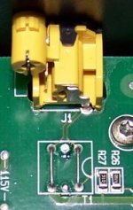
I just turned the D20 into a class 1 device by connecting PE. Instead of soldering a bit of wire between the pcb and the PE pin, I chose to do it as in the picture instead. This way I could experiment quickly and easily and it can be brought back into original state without soldering.
Whether or not PE is connected on the D20 seemed to have no effect on the noise-floor (I just turned up the volume on the amp all the way). According to this excellent article (http://www.diyaudio.com/forums/diya...udio-component-grounding-interconnection.html), "Loops aren’t bad – it depends on what is on the loop.", holds true.
I do have a groundloop, though, if I connect the CD-player to both the amp and the DAC. Then, at higher volume a buz/hum is heard, I presume this is a ground loop (CDP<>DAC<>AMP<>CDP). Connecting PE doesn't affect it.
I see on the pcb there's the possibility to connect SPDIF through an output transformer, that would prevent a ground loop. For now, I will either only connect analogue or SPDIF. The analogue output of the CDP is better than that of the DAC, so I prefer that, but if it goes bad again...
Attachments
Last edited:
What they have done is just incompetent and dangerous design. If no protective earth is present, the appliance MUST be double insulated. And having caps from a live side to case, without a protective earth, well it beggars belief. Are C2 and C3 Y rated?
using Y caps from L&N to circuit/chassis ground is common practice in classII devices with switching supplies. This is not a safety risk and inside the standard, if the leakage current does not excede something like 0,5mA.
Sometimes multivoltage supplies designed for the 115V world have higher than allowed leakage currents when used at 230V. Those fail European standards.
regards
Sometimes multivoltage supplies designed for the 115V world have higher than allowed leakage currents when used at 230V. Those fail European standards.
regards
What they have done is just incompetent and dangerous design. If no protective earth is present, the appliance MUST be double insulated. And having caps from a live side to case, without a protective earth, well it beggars belief. Are C2 and C3 Y rated?
I agree with you, but apparently it's allowed...
Yes, they are Y rated.
using Y caps from L&N to circuit/chassis ground is common practice in classII devices with switching supplies. This is not a safety risk and inside the standard, if the leakage current does not excede something like 0,5mA.
Sometimes multivoltage supplies designed for the 115V world have higher than allowed leakage currents when used at 230V. Those fail European standards.
regards
This might explain why Primare can do this. I believe that the filter pcb was designed to be used in their more expensive equipment with balanced connections. Those would be connected to PE. The current CD21 seems to be, it has balanced digital out (AES/EBU). The photos indeed show a yellow/green wire going to the chassis from the PE pin.
My D20 has the power transformers mounted on the main pcb. They have 2x 115 V primary windings which can be connected in parrallel or in series by bridging the correct tracks on the pcb. Obviously this does not affect the filter pcb which sits in front of the main pcb, so this must have been designed to stand 220-240 V.
I decided to keep PE connected to the chassis, so I don't get bitten again if I'm not careful. Besides, without focusing my attention on it, I noticed the sound quality seems to have improved slightly. The sound is somehow cleaner.
And... the analogue stage hasn't misbehaved since connecting PE (the fault is that it starts to produce nothing but white noise at a random point in time that can only be cured by switching it completely off and on again, until it starts again. That can be 5 mins. or 5 hours.). But I won't know for sure until quite some time has passed without it occurring. I'm keeping my fingers crossed.
The caps may be allowed and at least they used the right ones, but the equipment is still in breach as there is no protective earth, no double insulated symbol, and from the looks of it no double insulation either.
Good luck with your progress. I still think you should tell on them 😀
Good luck with your progress. I still think you should tell on them 😀
Last edited:
The caps may be allowed and at least they used the right ones, but the equipment is still in breach as there is no protective earth, no double insulated symbol, and from the looks of it no double insulation either.
Good luck with your progress. I still think you should tell on them 😀
I'm wondering what "double insulation" actually means. It and the double square symbol suggest two layers of insulation, but that's probably a bit naive.
It probably has more to do with passing certain electrical and mechanical tests than with physically having two insulating layers. Presumably these tests are tougher than for a class 1 device.
I assume the D20 passed these tests, but indeed, the double square logo should have been on it.
usually all double insulated equipment sold here, comes with a twin pole wire carrying the so called 'euro' plug.
I would distrust classII devices with a three pin IEC socket. It still may be legal, but I don't think it is a sign of design competence. 😉
Double insulation refers to have two independent insulations, one may be air, or to a single enforced insulation. Those insulations must protect people touching the device, even if major internal faults occour.
usually all double insulated equipment sold here, comes with a twin pole wire carrying the so called 'euro' plug.
I would distrust classII devices with a three pin IEC socket. It still may be legal, but I don't think it is a sign of design competence. 😉
Double insulation refers to have two independent insulations, one may be air, or to a single enforced insulation. Those insulations must protect people touching the device, even if major internal faults occour.
I agree with you completely. Sadly the three pin IEC socket is to be found on way too many class II devices. Looking at some pictures on the Italian website I linked to in a previous post, I see it's not just relatively unknown manufactureres that do this, but also the "big boys" like Accuphase, Denon, Harman Kardon, Pioneer, Yamaha, to name just a few of the pictures I just looked at...
Equipment like this is not tested, but self certified by the manufacturer.
The Y caps are limited in value so that the leakage current is not lethal even if an earth becomes disconnected. Otherwise you have to have a PERMANENT safety earth, not a plug
The Y caps are limited in value so that the leakage current is not lethal even if an earth becomes disconnected. Otherwise you have to have a PERMANENT safety earth, not a plug
Also, in class 1 devices, the PE must be connected to a post as close to the mains entrance as possible. This post must not be accessible from outside the device, i.e. one shouldn't be able to loosen it by e.g. unscrewing it. Yet some of our customers simply employ a faston connected to a central earth point on the back panel of the device to connect the PE pin of the mains entrance. This earth point can be loosened from the outside as the screw-heads are accessible. Still, it's sold all over the world, assuming that local authorities found it to comply with regulations...
I was under the impression that a fixed post was not required and a bolt of M4 or bigger is OK, but it must be close to the socket, not used as a fixing and not used for any other purpose than protective earth, and be protected against vibration loosening etc e.g. by nyloc nut or shakeproof washer. It must be marked as PE. The wire from the socket terminal to post must be crimped (to avoid solder melting and loosening) and withstand 20A or greater. Have you got any references for the fixed post?
Welcome to my world.😉Besides, without focusing my attention on it, I noticed the sound quality seems to have improved slightly. The sound is somehow cleaner.
Next, you may even start re-arranging your line cords and IC's to minimize trapped loop area...go figure..😀
On your ground connection..
I see the energy storage device under the panhead screw, that is good.
Is that a self-tapping screw that goes into the chasis metal?
Is the hole in the pcb solder coated, so that you are compressing solder with the screw? If so, that is not recommended as the solder will creep over time, loosening up the bond.
Oh, btw...excellent call on the reversed wires on the other thread...Well done.
Cheers, John
I was under the impression that a fixed post was not required and a bolt of M4 or bigger is OK, but it must be close to the socket, not used as a fixing and not used for any other purpose than protective earth, and be protected against vibration loosening etc e.g. by nyloc nut or shakeproof washer. It must be marked as PE. The wire from the socket terminal to post must be crimped (to avoid solder melting and loosening) and withstand 20A or greater. Have you got any references for the fixed post?
I based what I wrote on the following passage from David Davenport's article:
From IEC 60950, “The wire is terminated with a closed loop connector which is fixed to the earthing stud or screw with a star or lock washer and a nut. Other parts of the product that need to be earthed are connected by closed loop connectors to the same stud and locked with an additional nut. It is important that the earth wire from the power supply cord is located at the bottom of the stud and locked with its own nut. The earthing stud must not be used for any purpose other than earthing. It cannot be used, for example, for the mechanical fixing of parts other than the earth conductors. Its mechanical structure must also be such that it cannot be loosened from outside the device. For example, it cannot be a post fixed with a screw from outside the product.”
I interpret this in the following way: any post fixed by a bolt, or a long bolt used as a post, that is accessible from the outside of the finished product (e.g. a bolt- or srewhead sticking through a back panel) is not allowed.
In other words, allowed are posts that have been (e.g.) welded to a panel or fixed by a bolt with a head that is not accessible from outside the finished product.
Ah, I interpret that as you can't use a post that is held in place against the chassis by a bolt that is accessible from the outside. Like a PCB spacer sort of thing.
A bolt that is used as the post itself can be used if it is locked against the chassis, such as by two nuts. Ideally though a welded stud or similar would be the ideal.
A bolt that is used as the post itself can be used if it is locked against the chassis, such as by two nuts. Ideally though a welded stud or similar would be the ideal.
- Status
- Not open for further replies.
- Home
- General Interest
- Everything Else
- high potential on chassis CD-player