For those less mathematically inclined....
... I did a write-up following an other discussion which looks at it from another perspective : How to be on-time all the time.
jan didden
... I did a write-up following an other discussion which looks at it from another perspective : How to be on-time all the time.
jan didden
Sch3mat1c,
Yes distortion goes down, however what effect does the feedback have on the original signal. There is canceling of harmonics in this process. As others have said no NFB seems to "sound better" than systems with NFB. There is something "missing" between the two. The feedback is normally through a capacitor and resistor network. These are as you say non linear. I would prefer the term "frequency selective" or frequency dependant. There is a phase shift across a capacitor (in simple terms, that’s how a single phase motor uses a run winding). Agreed the phase shift is in place for the feedback and the signal, however the signal sees it once. the feedback sees it twice. The rise time of any signal will be shifted at each stage.
I would be interested in your thoughts
Regards
M. Gregg
Yvesm,
Do you have a preference to feedback?
Regards
M. Gregg
He he !
First work on individual stage for the better linearity and bandwith (this implicitly means "lowest phase shift").
This may need to use NFB at stage level althought it may happen that PFB (bootstrap) may improve both gain and linearity of a triode but doing that on a single stage is not so easy and a CCS could do the trick as well.
Designing balanced (understand PP) from input to output sometimes helps a lot because you always have the signal and its phase inverted image and so you can pick it up and put it in with the polarity you need to acheive either NFB or PFB.
In short, make the PI the first stage.
Balanced topology has almost always a better PSRR than singe ended, that may lighten a lot the PSU design.
Use as few stages as possible.
Now, put them all together and use GFB to tailor output impedance the way your loudspeakers ask for.
Do what I do, not what I say 😛
Yves.
Just another thought,
As SY said it does just what it says on the tin " It feeds back". Not in the calculation: what happens to hum at the output which is not in the input signal.
How does negative feedback do its "magic". If we have an out put Tx with bad high frequency response does the feedback "know this" or is it just going to "distort" the amplitude of the high frequencies or cut the low on the input section to compensate for the "cut" at that frequency on the output Tx.
Regards
M. Gregg
Wich means that local feedback could be good for the signal, but not the GLOBAL feedback! Right?Just another thought,
As SY said it does just what it says on the tin " It feeds back". Not in the calculation: what happens to hum at the output which is not in the input signal.
How does negative feedback do its "magic". If we have an out put Tx with bad high frequency response does the feedback "know this" or is it just going to "distort" the amplitude of the high frequencies or cut the low on the input section to compensate for the "cut" at that frequency on the output Tx.
Regards
M. Gregg
Silvino
Wich means that local feedback could be good for the signal, but not the GLOBAL feedback! Right?
Silvino
No. How do you come to that conclusion?
If you have some hum in the output even very small,what happens if you inject it in the input, where you should not have hum ?No. How do you come to that conclusion?
If you have some hum in the output even very small,what happens if you inject it in the input, where you should not have hum ?
The hum gets less. Feedback decreases everything that is in the output that is not in the input. Feedback doesn't 'inject it in the input' the way you imply. It (in opposite phase) injects a signal that gets (in opposite phase) amplified so as to cancel the unwanted signal.
jan didden
An apropos and entertaining treatment of this in fiction is the delightful short story "Silence, Please" by Arthur C. Clarke, in the collection "Tales from the White Hrt." Recommended reading.
If you have some hum in the output even very small,what happens if you inject it in the input, where you should not have hum ?
Keep in mind the feedback signal is a smaller (negative) version. Since there is no (practical) delay in the signal path, the negative image is amplified and travels through the amp canceling the a high percentage of unwanted positive products, including humm, that are not in the original signal. Some gain is lost because the original signal is in the feedback. But that is a small price to pay for cleaner output.
Last edited:
Sorry for my little knowlege about this subject but i am not a specialist or electronic engineer ,but just a newbie ,trying to learn more about this beautifull electronic component (Vacum Tube).I dont know if is possible with mathematics ,define how an amp sounds with and without NFB.
And also my english is not the best.
Best regards
Silvino
And also my english is not the best.
Best regards
Silvino
Sorry for my little knowlege about this subject but i am not a specialist or electronic engineer ,but just a newbie ,trying to learn more about this beautifull electronic component (Vacum Tube).I dont know if is possible with mathematics ,define how an amp sounds with and without NFB.
And also my english is not the best.
Best regards
Silvino
el156,
This is how you learn. You have to ask questions to expand your understanding.🙂
Keep asking and stick with it!
The best way to think about it is : If you have an input signal lets say +1V Pk and add negative feed back -1V Pk the result is 0.
The negative feedback is inverse of signal. However if the feedback is selective (non linear) then all frequencies are not covered equally. Capacitors, inductors, and resistance create filters that have a pass frequency. (the frequency the components like to let through) a bit like tuning a radio, they are not linear.
Kind regards
M. Gregg
Last edited:
I don't fully know the root cause of phase shift but I know it when I see it. Looking at the 1st and the 2nd stage of a guitar amp I build it certainly looks like delay on the scope. I believe this shift is from the caps in the tone section.
If I didn’t know about the speed of light thing I would insist that it was delay. Sometimes what you see is not what it looks like.
If I didn’t know about the speed of light thing I would insist that it was delay. Sometimes what you see is not what it looks like.
I don't fully know the root cause of phase shift but I know it when I see it. Looking at the 1st and the 2nd stage of a guitar amp I build it certainly looks like delay on the scope. I believe this shift is from the caps in the tone section.
If I didn’t know about the speed of light thing I would insist that it was delay. Sometimes what you see is not what it looks like.
As you say phase shift is not frequency change. The rise time of the slope is further along the time line.🙂 e.g 3 phase power each phase is out of phase with each other phase there is no change in frequency.
Regards
M. Gregg
Last edited:
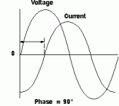
This is what you are seeing!🙂
O.k we have to assume amplitude is the same and both waveforms are voltage.
This is just a quick pic for discussion.
The arrow shows the out of phase. Does it show time lag?
Regards
M. Gregg
O.k we have to assume amplitude is the same and both waveforms are voltage.
This is just a quick pic for discussion.
The arrow shows the out of phase. Does it show time lag?
Regards
M. Gregg
Attachments
Last edited:
Thank you !
Maybe the best thing to do is make a tube amplifier,use it to listen to my prefered music (jazz) ,and dont worry about phase shift,delays,and other technical issues.If it sounds nice to my ears,then its OK !
All the best
Silvino
Maybe the best thing to do is make a tube amplifier,use it to listen to my prefered music (jazz) ,and dont worry about phase shift,delays,and other technical issues.If it sounds nice to my ears,then its OK !
All the best
Silvino
Post #76 shows phase shift. Whether this is caused by a time lag would depend on what happens to other frequencies. Time lag is equivalent to a phase shift which varies linearly with frequency.
This sort of thread crops up every few weeks. Why don't people read the textbooks before deciding to argue about their contents? For example, resistors and capacitors are more or less linear; a change in phase or frequency response is not a non-linearity.
Some facts:
1. A perfect distortionless amplifier does not need feedback to reduce distortion, but it may use feedback to reduce output impedance or broaden bandwidth. This feedback will not introduce distortion.
2. A very good amplifier, with very low distortion, may use no feedback or a little feedback. My guess is that many listeners would not be able to tell the difference. As the basic distortion is low, the higher order terms produced by the nonlinearity mixing signal with feedback will be even lower so not a problem.
3. An OK amplifier, with moderate distortion (such as a typical SE), may use no feedback or significant amounts of feedback - partly a matter of taste. If used with low levels of feedback it will definitely sound worse than 'no' or 'lots'. This is because the amp will mix signal with residual distortion in the feedback and produce higher-order products, whcih then need lots of feedback to reduce them sufficiently.
4. A 'poor' amplifier (typical SS?), with high distortion, must use high levels of feedback but if done carefully the result can be very good. This requires that the amp has plenty of open-loop gain even at frequency extremes, but it does not require that the open-loop bandwidth meets or exceeds the signal bandwidth. There will be lots of higher-order stuff, but we can force them to be small by using lots of feedback provided that nothing nasty like slew-rate limiting gets in the way.
Note that a good valve P-P amp will be somewhere between 2 and 3 - lower open-loop distortion than SE, so it doesn't need lots of feedback to reduce distortion but it might need it to reduce output impedance.
This is what you are seeing!🙂
O.k we have to assume amplitude is the same and both waveforms are voltage.
This is just a quick pic for discussion.
The arrow shows the out of phase. Does it show time lag?
Yes, in a sense it does. Maybe it's already been stated this way (if so, my apologies): The poster asked about signal delay time, and as stated by others, the signal transmission time is very very short compared to audio frequencies - so short it can be ignored.
But phase shifting is not related to the time it takes a voltage signal to be transmitted across a distance. Phase shifting is a caused by circuit components that store charge. In a pure resistor, voltage is exactly and instantly proportional to the current through it. If the current is constant, the voltage is constant. If a fixed current flows into a capacitor, the rate of change of voltage is constant.
Example: Take a 1 ohm resistor and a current source that instantly switches from zero to A over 1. The voltage will instantly jump from 0 to 1V. No delay (at least compared to audio frequencies) .
Now take a 1 farad capacitor and do the same thing. The voltage will rise linearly to 1V over 1 second. That's what causes the phase shift, or delay in the waveform.
(BTW, after 1 second, the voltage will rise to infinity or to the limit of current source or capacitor voltage rating. Let's use a true current source and a 10V cap, cause it's more fun that way - after one second - BANG!!!!)
Same phase shift principle applies to inductors. It takes time for current to charge it up.
Sheldon
. . .
Note that a good valve P-P amp will be somewhere between 2 and 3 - lower open-loop distortion than SE, so it doesn't need lots of feedback to reduce distortion but it might need it to reduce output impedance.
My faith 🙂
- Status
- Not open for further replies.
- Home
- Member Areas
- The Lounge
- Feedback Delay Time