I think his PS is still screwed up.
Hook your neg meter lead to the neg spkr terminal and measure each rail.
Hook your neg meter lead to the neg spkr terminal and measure each rail.
Last edited:
I'm wondering if he has all the grounds going back to the PS neutral. They are not connected on the board.
My eye lids are getting heavy, I missed my nap today.
My eye lids are getting heavy, I missed my nap today.
That would kill the CCS. Wouldn't that be cool if all he needs to do to make it work is connect the board ground to the PSU ground?
I'm wondering if he has all the grounds going back to the PS neutral. They are not connected on the board.
Hi Bill, can you clarify this, right now I'm confused when you say they are not connected to the board. If you watch the pictures have GND coming from xlr and switch to GND on the board and then to chassis. The ground connection in the front of the main board to chassis. At PS, have GND from cooper plate and from the AC inlet to chassis . Please I need to be clear on this before I take another step. I suspect something wrong here


Last edited:
Yes , it is connected to gnd and at the junction of z5 and R12.R13 - is that top to ground?.
This probably won't help much, but the fuse MUST be in front of the switch.
Why do you have the bleeders from the positive supply to the negative supply? They should be across the caps (+ to gnd, - to gnd).
Why do you have the bleeders from the positive supply to the negative supply? They should be across the caps (+ to gnd, - to gnd).
Thanks Rodeodave, but I'm just a copycat  Maybe the Thermostatic Switch have to be connected to the fuse not to power switch 😕
Maybe the Thermostatic Switch have to be connected to the fuse not to power switch 😕The idea of a fuse is to cut the mains voltage in case of anything going wrong, and that includes the switch. With the current situation (line filter, switch, fuse), if something goes wrong with the switch, a slight short or something, it will be up to the main circuit breaker to cut the power, and until that happens unpleasant things could happen. Putting the fuse in front of the switch solves the problem. Also if you accidentally touch the poles of the switch you then have additional protection by the fuse.
Another thing I would do differently is the way the circuit is earth-grounded, it looks as if it's done directly. I would do it via a thermistor, like the FirstWatt amps.
Also I would break up the loop in the capacitor bank. You are using two links to join the capacitor's grounds, you only need one. The best place to earth-ground the PSU and also to return the circuit ground to the PSU is at the first pair of capacitors. I'd put the ground link there, the earth connection and the circuit ground (coming from the pcb).
But these are just details (except for the fuse, to me it's safety issue), and I believe they're not the cause for the blown fuses.
The thermo-switch can be anywhere after the fuse (but within the xformers primary of course).
I hope you/we find the source of all the trouble, it's a very nice pair of amps you are building!
Hi Bill, can you clarify this, right now I'm confused when you say they are not connected to the board. If you watch the pictures have GND coming from xlr and switch to GND on the board and then to chassis. The ground connection in the front of the main board to chassis. At PS, have GND from cooper plate and from the AC inlet to chassis . Please I need to be clear on this before I take another step. I suspect something wrong hereView attachment 194333
View attachment 194334
It is clear from your previous picture of the PCB that the input grounds and output grounds are not connected to each other on the board. If the amp is to work they must be connected together, either through a jumper wire, or by connections from both ground traces back to the power supply neutral. As you have probably noticed I call the power supply -0- the neutral because it is not a true ground.
The chassis should be directly connected to the line input ground, and the circuitry should be connected from the power supply neutral through an isolation device such as a CL60 thermister to the chassis or directly to the line input ground. The actual grounding has absolutely no effect on the operation of the amp, but ALL the circuitry absolutely has to have a reference to the power supply neutral or it just will not work.
Someone else may be able to explain it in simpler terms, but I do not know how at this time.
You never did tell us what your rail voltages are, measured from the spkr neg term to each rail.
Thanks Rodeodave, I understand what you say about safety, going to change the place of the fuse and also going to change earth grounding as you and Bill commented. Bill, I don't have words to tell you how thankfully I Am with your help, please look at the picture to see if I understood you correctly. Thank you guys. 

Sorry! I'll do it.You never did tell us what your rail voltages are, measured from the spkr neg term to each rail.
They way you have redrawn the diagrams looks good.
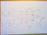
Second picture, greenish line (ground)...use separate wires for input-ground and output-ground, and run them to the first capacitor (I mean the first capacitor after the rectifier bridge, either one). There, at 1st cap, is the best spot for your main grounding point (lowest impedance). Here you join in-gnd, out-gnd, the link between pos and neg ground (you only need one link), and from there you also earth-ground the PSU through a CL60 thermistor.
This way you provide separate paths for all the currents, like charging pulses through the caps, return currents from the speaker, and seperate input gnd reference.
If you want I can draw a picture.
I agree, that's better, and use one point on the PS neutral to bring your grounds to, as Dave has said.
You can now remove the CL60 on the line input ground terminal and connect the line ground directly to the chassis for maximum safety.
Now if your PS is OK and your rail voltages are +45 and -45 you should have around a 39v drop across R13. Also your DC offset across the spkr terminals should be close to zero, +-50mv or so.
Thanks Rodeodave , that is a great advise , I'm going to implement this , but before, have some questions, excuse me if in some way is stupid but confuse about the draw, that is for stereo setup? (pairs of -IN and -out).Also I don't see ground returning to the board, and third I'm using 6 caps and hooked the inductors at second and third caps, is this way a disadvantage to the way like you did in the picture. Thanks again your great!!They way you have redrawn the diagrams looks good.
Second picture, greenish line (ground)...use separate wires for input-ground and output-ground, and run them to the first capacitor (I mean the first capacitor after the rectifier bridge, either one). There, at 1st cap, is the best spot for your main grounding point (lowest impedance). Here you join in-gnd, out-gnd, the link between pos and neg ground (you only need one link), and from there you also earth-ground the PSU through a CL60 thermistor.
This way you provide separate paths for all the currents, like charging pulses through the caps, return currents from the speaker, and seperate input gnd reference.
If you want I can draw a picture.
Hi Bill, again thanks to take the time for this, later I'll remove the CL60 and will implement all changes that you and rodeodave suggest. Ok now I took some measures and still have the problem, recheck PS, voltages were fine, secondaries no load 37.7 vdc , then voltages from spkr - (output) to -v 52.5 vdc and to +v was -5.72, across R13= 5.12 vdc and across -v and +v = 45 vdc.I agree, that's better, and use one point on the PS neutral to bring your grounds to, as Dave has said.
You can now remove the CL60 on the line input ground terminal and connect the line ground directly to the chassis for maximum safety.
Now if your PS is OK and your rail voltages are +45 and -45 you should have around a 39v drop across R13. Also your DC offset across the spkr terminals should be close to zero, +-50mv or so.
Dave just accidentally drew two channels instead of one, ignore it.
Your PS is totally screwed up. You should have around +50 DC from the neg spkr term to the pos rail, -50 to the neg rail, and 100 volts from pos rail to neg rail.
Disconnect all 4 secondary leads from the bridges and measure the AC voltage of each pair. If they are not very close to the same there is no logical reason to go any further, your trafo is bad. They should measure around 35 volts AC or whatever the trafo label says.
Only if they are the same should you proceed any further.
Disconnect all the DC connections from the bridges and reconnect the bridges to the secondary trafo leads. Measure the DC voltage at each bridge output from plus to minus. If they are not very close to the same, one of the bridges is bad or the trafo is bad.
If things still check out correctly at this point then either you have seriously miswired the filter section or one or more of your caps is bad. Disconnect the amp board from the power supply until you have a properly working power supply. There is absolutely no reason to go any further until you do.
Last edited:
One weird thing or maybe not , with the side that measured 41 vdc with secondaries and a bank of caps connected to bridge took a measure to the other secondaries no caps no bridge, sec, directly to the meter is getting 75 vdc.why the rise in dc voltage, if I don't have the transformer connected to the bridge, when before I was getting 28 vdc .Something wrong here?
did you measure at the trafo sec? and got 75Vdc?
you must measure Vac at this point.
- Status
- Not open for further replies.
- Home
- Amplifiers
- Pass Labs
- My Dream Aleph 2 Coming True