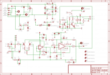
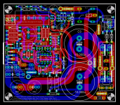
Here's the schematic and PCB layout for a successor to the MyRef RevC - it's basically very similar to the MyRef RevC, with a minor change derived from an idea used in the Musical Fidelity MVT.
Basically, the idea is to bypass the darlington LTP of the LM318, and use a lower-noise (and maybe faster and more linear) discrete LTP instead. I'm suggesting NEC 2sc1845 with 390 ohms degeneration on each leg, and a 33k resistor to set the tail current (which should improve H2 compared to an active current source) - these values are just placeholders, which will be tweaked after prototyping and auditioning. I expect that the change will result in darker silences and improved dynamic range over the RevC, which should be discernible on quiet passages.
Basically, the idea is to bypass the darlington LTP of the LM318, and use a lower-noise (and maybe faster and more linear) discrete LTP instead. I'm suggesting NEC 2sc1845 with 390 ohms degeneration on each leg, and a 33k resistor to set the tail current (which should improve H2 compared to an active current source) - these values are just placeholders, which will be tweaked after prototyping and auditioning. I expect that the change will result in darker silences and improved dynamic range over the RevC, which should be discernible on quiet passages.
Attachments
Hi,
how does the 4780 allow increased power?
As I see it, 4780 has half the heatsink interface area allocated to each chipamp channel.
how does the 4780 allow increased power?
As I see it, 4780 has half the heatsink interface area allocated to each chipamp channel.
Having in mind that a 4780 equals two 3886, it will be needed to bridge or parallel two of them, which will make a new complete design.Any chance in a future MyRefC to use the LM4780 to increase power?
Or you can experiment with two equal MyRefC modules by paralleling or bridging them, but I am not in favour of making experiments without deeply knowing the design.
Regards,
Regi
It's possible to use 2x LM3886 or 1x LM4780 as two Howland current pumps in parallel, with current sharing at the output through the 0.47 ohm resistors. In my sims, I found (quoting from memory) that the R5, R6, R8, R9 resistor networks have to matched across the two parallel Howlands to about +/- 0.01% to get the current sharing to match to about 95% (at 20 kHz).
It's feasible, but it doesn't buy much. The voltage rails are still constrained to about +/- 35V, so about all that the parallel Howlands succeed in obtaining is the current-drive to drive 4-ohm loads. Compensation still has to be tweaked for the 4-ohm load, but that's probably manageable.
You could probably get 80 to 100W into 4 ohms. It's still going to remain 40 to 50W into 8 ohms.
Last edited:
Something like Twisted Pear's Sympatico,
"Sympatico is a single small module per channel with one LM4780 dual amplifier chip in a balanced, bridged configuration" "100 + Watts/Channel into 8-ohm loads (conservative)"
The thought came from the Sympatico design,
"Sympatico is a single small module per channel with one LM4780 dual amplifier chip in a balanced, bridged configuration" "100 + Watts/Channel into 8-ohm loads (conservative)"
The thought came from the Sympatico design,
A bridged topology is different from a parallel Howland. In a bridged configuration, each chipamp is driven 180 degrees antiphase, while in a parallel Howland, both are driven in-phase.
A bridged MyRef is somewhat more complicated - it will require an additional LM318 to drive the second chipamp antiphase to the first. This LM318 has to have its own complete GNFB loop, along with all compensation elements, with adjustments to take care of the phase reversal on one half of the bridge.
A bridged-parallel MyRef topology is also possible, with 4x LM3886.
if you had two identical my-ref modules, will it be possible to bridge them by driving one of the inputs out of phase with the other and connecting the outputs of those two amps to a single 8 ohms speaker?
Is it necessary to have low noise resistor(which is connected from signal path to ground that works together with input coupling capacitor)?
if you had two identical my-ref modules, will it be possible to bridge them by driving one of the inputs out of phase with the other and connecting the outputs of those two amps to a single 8 ohms speaker?
If the PGND of the two modules is the same, i.e. shorted, then in principle it can be done.
However, note that the speaker protection relay is bypassed, and each LM3886 current-pump section is looking into an effective load impedance of 4 ohms, not 8 ohms. Both conditions are not conducive for long-term durability.
Is it necessary to have low noise resistor(which is connected from signal path to ground that works together with input coupling capacitor)?
I'm using 100k carbon-films as the input shunt resistors, and the thermal noise is inaudible.
The answer seems to be that it probably doesn't matter - though a 100k carbon-composition resistor may cross the audibility threshold.
If the PGND of the two modules is the same, i.e. shorted, then in principle it can be done.
However, note that the speaker protection relay is bypassed, and each LM3886 current-pump section is looking into an effective load impedance of 4 ohms, not 8 ohms. Both conditions are not conducive for long-term durability.
Yes, i agree that the relay is being bypassed this way. But isn't this similar to how two lm3886's in a typical/regular configuration is bridged, when you consider the impedance each amplifier sees and the heat that it dissipates?
... isn't this similar to how two lm3886's in a typical/regular configuration is bridged, when you consider the impedance each amplifier sees and the heat that it dissipates?
A single LM3886 driving a 4-ohm load is rated for rails of +/- 28V max. With 2 bridged LM3886s driving an 8-ohm load, the current through each chipamp is equivalent to a single chipamp driving a 4-ohm load. Hence, there can be no change in the maximum allowed rail voltages of +/- 28V for each chipamp.
The typical +/-32V rails used for the MyRef would exceed this limiting spec.
Half the impedance = twice the current = four times the dissipation.
If you need more power, consider the 4702 with an output pair of your favorite transistors and a single Vbe. It would give you 80W or so from 40-45V rails into 8 ohms, and quite a bit more at 4 ohms. I've done a BPA with the LM4780 (not this topology, more of a datasheet application) and it's good for what you spend on it, though not the best I've heard.
Besides, there's not as much subjective difference between 50 and 100W as you would think. A good 50 is much better than a mediocre 100.
Last edited:
the 100k carbon film any thing is paralleled by the output impedance of the source.I'm using 100k carbon-films as the input shunt resistors, and the thermal noise is inaudible.
Because the source's output impedance is probably only 1% of that 100k carbon anything the source impedance dominates the source noise. i.e. almost none from a couple of hundred ohms.
If the source is capacitor coupled then at very low frequency the impedance seen by the power amp looking back to the source rises. It rises so high at VLF that the 100k starts to dominate the LF noise. Fortunately we can't hear much of that.
I have a 2x25Vac transformer, will it be too high for lm4780?
25Vac x (240/230) x 1.414 rec = around 36Vdc.
the datasheet shown 25v 4ohm, 30v 6ohm and 35v 8ohm.
so I have to keep switching different sec voltage of transformer every time I pair the amp with different impedance of speaker for better sound? or the internal regulator of lm4780 will lower down the voltage when I plug 4ohm speaker into it?
25Vac is getting near the maximum supply voltage for a 3886. That's the chip used in this amplifier implementation.
I think you are in the wrong thread.
I think you are in the wrong thread.
Linux
Could you post a BOM for your RevD boards? Do you recommend your own choice parts or are you on the Dario and Madisonears bandwagon for the Ultimate BOM?
I have a guy who emailed you and is hoping to get RevD boards. Mitchell. He has no response yet but hope you can help him out.
Uriah
Could you post a BOM for your RevD boards? Do you recommend your own choice parts or are you on the Dario and Madisonears bandwagon for the Ultimate BOM?
I have a guy who emailed you and is hoping to get RevD boards. Mitchell. He has no response yet but hope you can help him out.
Uriah
Could you post a BOM for your RevD boards? Do you recommend your own choice parts or are you on the Dario and Madisonears bandwagon for the Ultimate BOM?
I have a guy who emailed you and is hoping to get RevD boards. Mitchell.
The RevD boards haven't been prototyped - I posted the layout here earlier, but I'm still undecided on whether to give that layout for manufacturing. Meanwhile, I decided to re-spin the RevC Version 1.3 board with layout changes, which will become RevC Version 1.4.
Here's the baseline premium BoM for the Version 1.3/1.4 RevC boards - there are a few minor changes from this BoM in the RevC premium kits that I've sold, and there will be a few changes in the future as some experimental mods are auditioned.
The BoM differs from Dario's/Tom's suggestions, but the version 1.3 PCB does support most of their choices - the only difficulty in version 1.3 was in C6, C11, C7 and C13 due to size or lead-pitch conflicts. Version 1.4 will accommodate the Ultimate BoM (except C13) more completely.
To get to RevD from this RevC BoM, add:
2 x 2sc1845 NPN small-signal BJTs
2 x 390R/0.25W 2% Panasonic carbon film resistor
1 x 33k/0.25W 1% MFR
Attachments
Last edited:
- Status
- Not open for further replies.
- Home
- Amplifiers
- Chip Amps
- MyRef RevD - successor to RevC