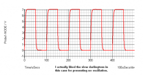
Rod Elliot said it quite loud in his Death of Zen power amp page. It's the test circuit he experimented with; using an NPN darlington as the power device and an 8ohm resistor as the current source. He seems quite unsatisfied with the output of this amp at its original state and noted that there will be chages in the final circuit. There were big changes including the omission of the darlington as they are slow. Everything went fine and the DoZ amp was born. I have made a couple of DoZ and it's an exceptional amp with unmatched sound quality, I like the amp. Link> Death of Zen - A new Class-A power amp
So far so good.
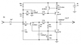
A couple of days ago I was going through that project page again and got stuck on that "STOP!". The test circuit seemed to me as workable with only the addition of a constant current source in the place of the 8ohm current source resistor. I added one, following the way the CCS is designed in the DoZ Preamplifier, using a PNP darlington and a BC560.
Expecting NOTHING special I assembled it and powered it up.
The amp really sounds nothing special, EXCEPT when I start varying the VR1. Damn funny things start to happen while I increase or decrease its value. Rod explains how the amount of distortion in this amp's output almost directly relates to the value of this resistor.
What I felt was that when the resistance of VR1 is set to high, the amp starts creating strange clipping behaviour, which sounds good to me when there is a little of it. Of course too much of it makes the sound gross and low volume and at 10Kohm almost nothing is heard.
The main source of fun right now is this resistor. At high, medium and low value this resistor makes this amp sound Distorted like an overdriven valve amp, Sweet like any SE amp, and Clean like a Hi-Fi respectively. You get the idea.
However, I believe you already know what this ameteur is babbling about.
Well, I am here to say thanks to the diyAudio community from where I have gained a lot of knowledge and enough courage to do experiment with existing ideas.
So far so good.
A couple of days ago I was going through that project page again and got stuck on that "STOP!". The test circuit seemed to me as workable with only the addition of a constant current source in the place of the 8ohm current source resistor. I added one, following the way the CCS is designed in the DoZ Preamplifier, using a PNP darlington and a BC560.
Expecting NOTHING special I assembled it and powered it up.
The amp really sounds nothing special, EXCEPT when I start varying the VR1. Damn funny things start to happen while I increase or decrease its value. Rod explains how the amount of distortion in this amp's output almost directly relates to the value of this resistor.
What I felt was that when the resistance of VR1 is set to high, the amp starts creating strange clipping behaviour, which sounds good to me when there is a little of it. Of course too much of it makes the sound gross and low volume and at 10Kohm almost nothing is heard.
The main source of fun right now is this resistor. At high, medium and low value this resistor makes this amp sound Distorted like an overdriven valve amp, Sweet like any SE amp, and Clean like a Hi-Fi respectively. You get the idea.
However, I believe you already know what this ameteur is babbling about.
Well, I am here to say thanks to the diyAudio community from where I have gained a lot of knowledge and enough courage to do experiment with existing ideas.
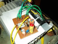
Attachments
Last edited:
Hi,
I think this explains what I felt too. I use VR1 with R 10k (Carbon, Takman), and I wonder why the sounds is quite harsh if the source volume is high although the rail voltage is quite high. But it seems that VR1 may impact to DC offset, so there will be no choice if we use no output capacitor coupling (using balance PSU, use ground as signal ground for input and output/speaker.
Any idea?
Ervin L
Currently I am not in the mood for that much of testing, with direct coupling or split supply etc. Actually I really love what comes out of that NipponChemicon output cap, kinda wanna keep it there... 🙂
I might do some simulations of your idea in the meantime.
I might do some simulations of your idea in the meantime.
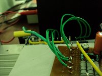
Attachments
Without feedback, VR1 would simply be setting the output bias, and hence the output quiescent voltage. Too high or low means distorted output as one of the devices would be either cutting off or bottoming.
With feedback, the main result would be to adjust the current through the input transistor and also vary the output voltage (but with smaller variations than before). So the wrong setting can cause assymetric clipping in the output stage, or non-linear distortion in the input stage (partly offset by the negative feedback, which will generate higher-order distortion too).
A rather strange circuit!
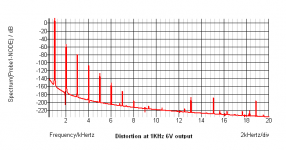
Yup quite strange. Tech details aside, it sounds (or at least simulates) very clean (as much as is usual for SE amps) starting from about 5Kohms and at about 1Kohm or so it's turned off.
The squarewave sim is of 10khz.
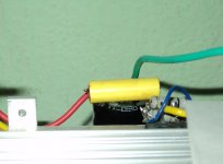
Yes I'll upload the realworld tests too. 🙂
The squarewave sim is of 10khz.
Yes I'll upload the realworld tests too. 🙂
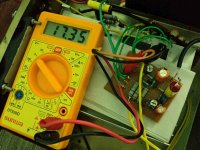
Attachments
Without feedback, VR1 would simply be setting the output bias, and hence the output quiescent voltage. Too high or low means distorted output as one of the devices would be either cutting off or bottoming.
With feedback, the main result would be to adjust the current through the input transistor and also vary the output voltage (but with smaller variations than before). So the wrong setting can cause assymetric clipping in the output stage, or non-linear distortion in the input stage (partly offset by the negative feedback, which will generate higher-order distortion too).
A rather strange circuit!
How is the circuit without feedback, as feedback (R) is needed by first transistor to get current (CFB)? Do you mean to connect this to some voltage reference instead of output?
Ervin L
I didn't say it was without feedback. I meant that if it did not have feedback then VR1 would simply be setting the output bias. As it does have feedback, the result is more complicated.
The early posters seemed puzzled by the effect of VR1. I was explaining what it does. When explaining a circuit, the presence of feedback can confuse things so it is often best to mentally break the feedback loop, explain the circuit, then impose the feedback again to get the full picture.
The early posters seemed puzzled by the effect of VR1. I was explaining what it does. When explaining a circuit, the presence of feedback can confuse things so it is often best to mentally break the feedback loop, explain the circuit, then impose the feedback again to get the full picture.
hello.
my opinion............there is a ccs (with q3,q4) that sets the (big) quiescent current trough the output transistors ............with vr1 you can set the out-volts(dc) to half - powersupply voltage or so (symmetric clipping)..........
greetings
my opinion............there is a ccs (with q3,q4) that sets the (big) quiescent current trough the output transistors ............with vr1 you can set the out-volts(dc) to half - powersupply voltage or so (symmetric clipping)..........
greetings
Last edited:
..........r7 is part of the input volts divider (dc) r8,r9, and sets the input impedance mostly........
...........r4 (2,2k) is the feedback resistor..........without this res you should get open loop gain?
.....late night here.
greets
:sleep
.....late night here.
greets
:sleep
Last edited:
mmm... I think disconnecting it from output and connecting it to the positive rail would do it. I may be wrong.
..........yes,not only "without"..........but try to connect a res to the psu rail or so (without using feedback).........
greetings
greetings
I hope no one else finds this Thread.
They will learn only gibberish.
Please excuse me DF, you tried hard to bring some sense back in.
They will learn only gibberish.
Please excuse me DF, you tried hard to bring some sense back in.
..........yes,not only "without"..........but try to connect a res to the psu rail or so (without using feedback).........
greetings
?!
I hope no one else finds this Thread.
They will learn only gibberish.
Please excuse me DF, you tried hard to bring some sense back in.
Why should only circuits be strange?
I have some hitachi laterals at hand and being an ameteur I always run a sim before trying a new circuit. Unfortunately I failed to find a model for the 2SK1058/2SJ162 and wanna try this circuit with them.
Do anyone have any idea how this circuit would behave if complementary lateral fets were used at the place of the darlingtons?
thanks.
Do anyone have any idea how this circuit would behave if complementary lateral fets were used at the place of the darlingtons?
thanks.
- Status
- Not open for further replies.
- Home
- Amplifiers
- Solid State
- STOP! - Do not build this circuit!