Hi Terry,
I think nobody can hear the difference between 10 or 1ppm distortion at 20kHz.
But for me, I like the intellectual challenge of breaking the 1ppm barrier.
Cheers,
E.
Hi, Edmond
At 20khz, it s quite a challenge assuming one wants
to retain excellent stability with the most weird loads.
but at moderate power, 20/50W rms, it s quite feasible...
Cheers
Attachments
Wahab, would you simulate a couple of F5 like circuits? One is a popular classic and another is an unknown next of kin. So we can see the distortion profiles in comparison to JLH and F5. I hope you have time and some same or alike models at a point.
Attachments
Wahab, would you simulate a couple of F5 like circuits? One is a popular classic and another is an unknown next of kin. So we can see the distortion profiles in comparison to JLH and F5. I hope you have time and some same or alike models at a point.
Hi, Salas
The one on the right is Hiraga s Monster..
Its sims can be found here :
http://www.diyaudio.com/forums/soli...-popular-amps-simulations-15.html#post2311257
The other one has GNFB restricted to the two first stages,
the output stage being open loop, although with a local NFB loop..
This kind of arrangement produce high Thd ratio, moreover
with lateral fets.
To add insult to injury, the complementary OPS will inevitably
cancel even order harmonics and let the odd ones as dominant,
particularly H3.
Unfortunately , i have not the models for the mos drivers..
I will check if i ve got some equivalents.
Last edited:
Nice, I haven't seen you had done the Hiraga already. I go see. Cheers. The other one is an obscure Jap's I found somewhere online some time ago.
The 1ppm barrier
Hi Wahab,
Agreed, it isn't that easy, but it's feasible if all possible tricks are employed. To name a few: ETMC, NDFL, HEC or auto bias with error feed back. The downside is that such an amp is quite complex (see the PGP amp, 60 trannies or so). Also the voltage and current clamps/limiters are far more critical and complex.
Cheers,
E.
Hi, Edmond
At 20khz, it s quite a challenge assuming one wants to retain excellent stability with the most weird loads. but at moderate power, 20/50W rms, it's quite feasible...
Cheers
Hi Wahab,
Agreed, it isn't that easy, but it's feasible if all possible tricks are employed. To name a few: ETMC, NDFL, HEC or auto bias with error feed back. The downside is that such an amp is quite complex (see the PGP amp, 60 trannies or so). Also the voltage and current clamps/limiters are far more critical and complex.
Cheers,
E.
Guys, what do you think of this ONKYO blah blah? Holds any water?
Somewhat paradoxal..
Non GNFB amp with loads of local NFB in the OPS..
Since the "no GNFB" marketing doesn t allow for such
error correction, the needed low THD ratio is preserved
by transferring the NFB to the output stage..
Hi Wahab,
Agreed, it isn't that easy, but it's feasible if all possible tricks are employed. To name a few: ETMC, NDFL, HEC or auto bias with error feed back. The downside is that such an amp is quite complex (see the PGP amp, 60 trannies or so). Also the voltage and current clamps/limiters are far more critical and complex.
Cheers,
E.
Hi, Edmond
As sole correction, i use GNFB , TMC and also some pole
cancellation for a total of 10 caps for compensation purpose,
including the one on the boucherot/zobel cell, as well as
22 bjts for the FE.
True that your PGP is surely the most tranny inflated one i ever saw,
to the point one may ask himself how you only managed to make it
work the way it did...
Anyway, quite a complexe exercise of style..
cheers,
Hi, Edmond
As sole correction, i use GNFB , TMC and also some pole cancellation for a total of 10 caps for compensation purpose, including the one on the boucherot/zobel cell, as well as
22 bjts for the FE.
Hi Wahab,
Indeed, that are more acceptable numbers (compared to the PGP amp). What's the THD20 of the FE, that is, with an idealized OPS?
True that your PGP is surely the most tranny inflated one i ever saw, to the point one may ask himself how you only managed to make it work the way it did...
Anyway, quite a complex exercise of style..
cheers,
Admittedly, the front end of the PGP amp is definitely over engineered, but syn08 demanded ultra low distortion. THD20 of the FE = 63ppb.
Cheers,
E.
Hi Wahab,
Indeed, that are more acceptable numbers (compared to the PGP amp). What's the THD20 of the FE, that is, with an idealized OPS?
Admittedly, the front end of the PGP amp is definitely over engineered, but syn08 demanded ultra low distortion. THD20 of the FE = 63ppb.
Cheers,
E.
Hi, Edmond
Well, i ve got about 300ppb with unloaded non ideal OPS at 20V pk
using TMC and 150ppb with TPC in the same conditions..
Since i have not ideal transistors models, i proceeded this way.
Also, i retained TMC since its impulse response please me more....
cheers,
As a special guest, the ULD amp proposed by Phoenix which is discussed
in these lines :
http://www.diyaudio.com/forums/solid-state/142166-new-amplifier-uld-extreme.html
Since it has same basic topology as Ostripper AX2, the results are close.
All is a matter of quality of the design....
In both cases, performances are good.
in these lines :
http://www.diyaudio.com/forums/solid-state/142166-new-amplifier-uld-extreme.html
Since it has same basic topology as Ostripper AX2, the results are close.
All is a matter of quality of the design....
In both cases, performances are good.
Attachments
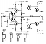
Next is an old CFB design with excellent results for who
is in search of Hiraga/Pass/JLH thd contents , but with
better perfs..
Original can be found in Motorola AN483 or in a german
publication, i don t know who is the first publisher..
I adapted a mosfet OPS that give better results than
the original EF2.
Quiescent current is 0.65A wich is low compared
to most classA designs.
Attachments
40W @ 8? 30dB gain, got something?
?..Class A black devil style ?...
You can adapt this one, increase PS to about 50V
and add a second pair of mosfets.
Iq can be kept the same, with 350ma/pair..
Of course, gain can be increased, as it s currently 20db;
Also, the bias voltage divider must be slightly readjusted.
I can send you an output DC coupled version using a
DC servo if you are interested.
and add a second pair of mosfets.
Iq can be kept the same, with 350ma/pair..
Of course, gain can be increased, as it s currently 20db;
Also, the bias voltage divider must be slightly readjusted.
I can send you an output DC coupled version using a
DC servo if you are interested.
Last edited:
By losing 10dB NFB will it do well still? How many Volt on 8R it can do now? 10 or 18? I see some specs in the pdf but I don't know German. Yes, if it can do over 50W with first 10W class A decently and being DC, why not, send. I have a friend with 20W tubes that needs double and more for his 88dB speakers but will cost much weight and expense to go 60W. Maybe he can try something logical SS and decide.
Hi abraxalito,
Some speakers are less kind to amplifiers than others. If you want to also look at phase problems along with the impedance variations, you've opened up quite a can of worms there. So, how to divide the blame?
You are trying to look at two ends of the same issue. On one hand, you have a poorly behaved load as far as an amplifier is concerned. Some amplifiers will react more than others and damping factor is only part of the story there. Believe me when I say that getting into this would create one of those threads that requires high maintenance.
On the other side, you have a speaker load that simply reacts to the voltage across it's terminals. It's behavior depends entirely on the applied voltage and it's internal complex reactions with air, moving mass and impedances. Forgive me if I left anything out. The speaker has no expectation of the future and it only "knows" what voltage is applied from moment to moment. Therefore, I guess we have to define distortion in the speaker as how it's actual acoustic radiation deviates from a linear response to a voltage applied to it's terminals. I'm calling the perfect response "linear" because I want to for purposes of my answer.
That leaves us with the amplifier being responsible for it's behavior due to a varying load. But there are limits to assigning distortion to voltage drops across it's output terminals. Damping factor improvements are one of those "diminishing returns" type things. You have a fixed contact resistance and wire resistance (they vary with temperature, but we'll call those steady state values). Once the output impedance in of the same magnitude of the connection plus wire resistances added together, further decreases in damping factor bring less and less improvement. The only other issues would be the ability of the power supply to supply enough current at voltage, and the internal traces, wire and circuit performing at a similar level that they do when not under load.
I think only a untrained engineer or hobbyist would intentionally design a loudspeaker system that is difficult to drive. Unhappy amplifiers tend not to sound their best, therefore causing poor sound whenever hard to drive speaker systems are connected. That type of speaker will not be commercially successful compared to designs that allow amplifiers to perform well.
But, that's just my opinion and also O.T. What is your point of view on your own question?
-Chris
I'm trying to figure out what you're getting at there.So Chris, what of speaker-induced distortion into the electronics? Given that speakers are a non-linear load, any non-zero impedance voltage source will have its output distorted by the loading effects. Does this count as an electronic problem? It can certainly be reduced electronically - by reducing the amplifier output impedance.
Some speakers are less kind to amplifiers than others. If you want to also look at phase problems along with the impedance variations, you've opened up quite a can of worms there. So, how to divide the blame?
You are trying to look at two ends of the same issue. On one hand, you have a poorly behaved load as far as an amplifier is concerned. Some amplifiers will react more than others and damping factor is only part of the story there. Believe me when I say that getting into this would create one of those threads that requires high maintenance.
On the other side, you have a speaker load that simply reacts to the voltage across it's terminals. It's behavior depends entirely on the applied voltage and it's internal complex reactions with air, moving mass and impedances. Forgive me if I left anything out. The speaker has no expectation of the future and it only "knows" what voltage is applied from moment to moment. Therefore, I guess we have to define distortion in the speaker as how it's actual acoustic radiation deviates from a linear response to a voltage applied to it's terminals. I'm calling the perfect response "linear" because I want to for purposes of my answer.
That leaves us with the amplifier being responsible for it's behavior due to a varying load. But there are limits to assigning distortion to voltage drops across it's output terminals. Damping factor improvements are one of those "diminishing returns" type things. You have a fixed contact resistance and wire resistance (they vary with temperature, but we'll call those steady state values). Once the output impedance in of the same magnitude of the connection plus wire resistances added together, further decreases in damping factor bring less and less improvement. The only other issues would be the ability of the power supply to supply enough current at voltage, and the internal traces, wire and circuit performing at a similar level that they do when not under load.
I think only a untrained engineer or hobbyist would intentionally design a loudspeaker system that is difficult to drive. Unhappy amplifiers tend not to sound their best, therefore causing poor sound whenever hard to drive speaker systems are connected. That type of speaker will not be commercially successful compared to designs that allow amplifiers to perform well.
But, that's just my opinion and also O.T. What is your point of view on your own question?
-Chris
Of course, the 1ppm figure is load dependent, but basically, that doesn't change the challenge.
Well my interest was in the extent of focus on getting a low output impedance so that the figure would be less determined by the load. Like for example do you think its worth spending time getting the OP impedance well into sub-milliohm territory? And if so, at all frequencies across the band?
- Status
- Not open for further replies.
- Home
- Amplifiers
- Solid State
- Diy audio popular amps simulations