Thanks for that tip, I will try it today...Krisfr
If you get the pcb of Luka's supply from this thread and print it on a laser printer,take to any printshop,Kinko's or other even your high school photolab can make you a negative or a postive transfer(make sure its a mirror image)Hold the pcb up to a light source to check.Then you can process it and start soldering parts.
That makes a lot of sense...
I don't know how PCB houses are with negatives, but you sure do pay them, just not sure if you can get them
A 110 Volt design with ETD49
I am going to do a 110 volt design slowly and build it with the idea of incorporating ALL that I have learned by reading this thread. I have some parts but want to do a LTSpice to make sure I am in the correct ball park.
I have time and I am not in a hurry. Just want the ducks in a row before I shoot off my gun.
MANY thanks to ALL for input and advice...
Luka"s SMPS
Hello from Croatia! I am new here and quite interested about Luka"s SMPS. It is great design, as far i can uderstend SMPS, and i will like to make one as PSU for my audio amplifier. Amp is build around TDA 7294, so power demand for that type of amp will be +/- 30-35v and 10 A peak(in stereo). I explored this topic from very beginning but i still have some questions about output transformer. Well, what tipe of awg wire to use for pri & sec windings, and how to winde then, and how many turns. for example:
pri: 26 turns of 3x19awg
sec: 2x12 turn of 5x19awg
layers:
1/2 prim + 1/2sec + 1/2prim + 1/2prim
or
1/2prim + whole sec + 1/2prim.
Is there any kind of formula so i can calculate for my self?
Tnx guys in advance...
P.S.
and of course i will post pic"s of my work here, as soon as i get it done.
Last edited:
26 turns for etd44 is perfect, I have this right now (making is regulated finally, for same output voltage as yours)
12 turns for secondary is too much, I have 6 and I get something like +/-35 (I will use pfc for my).. I would use 7 for each sedondary
You do your trafo like this: 0.5 primary, both secondarys(or more if you have them, all that are high current) and then last part of primary
So this looks like this, 13turns, 2x 7, 13 turns
there are a lot of equations out there, just be sure to find one that is right, and you don't mix american and our units
i'll be waiting for pic's 🙂
Great!. Tnx Luka. I have it clear now. One more question😀, i notice on asembled one a little trim pot standing on that little external board (near that TL). Is that R3 - 56k? What are you adjusting with it? You mentioned PFC as you upgrade, look in this PDF maybe you find somting interesting. 🙂
Cheers....
Download PFC.pdf, upload your files and earn money.
Cheers....
Download PFC.pdf, upload your files and earn money.
Anyone with some tips on preparing and or cleaning the end of the litz wire for soldering to the studs on an ET-49 or other transformer? Any help or hints for the overall process would be appreciated...
Anyone with some tips on preparing and or cleaning the end of the litz wire for soldering to the studs on an ET-49 or other transformer? Any help or hints for the overall process would be appreciated...
Hi Krisfr,
here is one nice article about soldering litz wire. Maybe you find it intereting. 🙂
URL: 41Hz Audio - Soldering Litz wire
Hi Krisfr,
here is one nice article about soldering litz wire. Maybe you find it intereting. 🙂
URL: 41Hz Audio - Soldering Litz wire
Perfect....JUST what I needed to do the job.... THANKS
Great!. Tnx Luka. I have it clear now. One more question😀, i notice on asembled one a little trim pot standing on that little external board (near that TL). Is that R3 - 56k? What are you adjusting with it? You mentioned PFC as you upgrade, look in this PDF maybe you find somting interesting. 🙂
Cheers....
Download PFC.pdf, upload your files and earn money.
That whole board is feedback, which was not in use most of the time, while it was, that pot and yellow cap there, were not in use
I already have PFC, has enough power for me, but thanks
yes, that is easy, I just find it harder to do with smaller the wire getsPerfect....JUST what I needed to do the job.... THANKS
Update!
So I've been trying to make it regulated. I changed few components, add back coupled inductor, added filters, primary and seconday to kill the ringing as best as I could with components at hand.
And result is... around 50mV ripple looking both rails at the same time, that is ~+/-35v (load independent!!)
Load step from about 80w to 377w with probably only 0.1v drop and I say probably coz its that low. when on AC coupled, there this could be seen, but on 5v/div, and still seeing 70v there is no visible drop, rock solid.
So i am 😛 right now
Last edited:
hi luka,
i am planning to build your smps but with etd49 core.how did you calculate
your primary turns.iam coming with different results.here are my calculations.
input voltages =180-270 vac
output voltages =100 volts @ 5amp
output ripple =50mV p-p
power output =100x5=500w
power input =po/eff=500/0.8=625w
dc input vots
vin low =1.414x180=254 vdc
vin high =1.414x270=382
av input current
highest average current =500/254=1.96 amp
lowest average current =500/382=1.30 amp
max peak current
Ipk =2.8x500/254=5.51 amp
no of primary turns
npri=vin(max)x10^8/4xfxbxAc=382x10^8/4x50000x1600x2.11
=57 turns
these all are taken from marty browns 2nd edition
i have read bmax of 1600 is safe value i think its in pressmans book.
how do we find the safe value of bmax.i have read the book but some stuff
is going out of my mind.what value of bmax you are using
bsat is determined after finding the no of primary turns .that means we already using the bmax value.
i have many questions .i cant remember right now.i have read the thread
twice.help me
thanks in advance
ravs
be a vegeterian.....
Bmax
Bmax value for ETD49 core is 1600? how is that?
hi luka,
i am planning to build your smps but with etd49 core.how did you calculate
your primary turns.iam coming with different results.here are my calculations.
input voltages =180-270 vac
output voltages =100 volts @ 5amp
output ripple =50mV p-p
power output =100x5=500w
power input =po/eff=500/0.8=625w
dc input vots
vin low =1.414x180=254 vdc
vin high =1.414x270=382
av input current
highest average current =500/254=1.96 amp
lowest average current =500/382=1.30 amp
max peak current
Ipk =2.8x500/254=5.51 amp
no of primary turns
npri=vin(max)x10^8/4xfxbxAc=382x10^8/4x50000x1600x2.11
=57 turns
these all are taken from marty browns 2nd edition
i have read bmax of 1600 is safe value i think its in pressmans book.
how do we find the safe value of bmax.i have read the book but some stuff
is going out of my mind.what value of bmax you are using
bsat is determined after finding the no of primary turns .that means we already using the bmax value.
i have many questions .i cant remember right now.i have read the thread
twice.help me
thanks in advance
ravs
be a vegeterian.....
Bmax value for ETD49 core is 1600? how is that?
The Bmax value is determined by the type of material the core is made from, the ambient temp of the core in full load, etc.
all of these you can find and calculate if you search the datasheet of the material.
for example 3C90, 3F3, etc
regards,
savu
all of these you can find and calculate if you search the datasheet of the material.
for example 3C90, 3F3, etc
regards,
savu
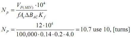
Vp min is half of the min DC voltage on input 128v or so.
f = freq. in Hz
Ac = core cross section in cm2, 1.73cm2 for etd44
Bac is let say half of the Bmax, in Tesla's, so 0,2T = 2000Gauss
Kf = 4 for squere waveform, other for others
For my was:
193v*10^4/(50000*1.73*0.21*4)= 26.56T, used 26
Is it in any way conceivable to make this supply work with 110 volts? OR is a whole new design needed? I too will be using a ETD-49.
Thanks and forgive the density of my understanding of this project.
Thanks and forgive the density of my understanding of this project.
Is it in any way conceivable to make this supply work with 110 volts? OR is a whole new design needed? I too will be using a ETD-49.
Thanks and forgive the density of my understanding of this project.
You only need to connect 2 points on pcb... any half bridge can be 110v or 220v. Do you know where you need to make short?
You only need to connect 2 points on pcb... any half bridge can be 110v or 220v. Do you know where you need to make short?
With bated breath YES YES YES
Thanks for ALL your hard work and expertise, while sharing it with the novices like myself.
Thanks
we are all learning 🙂
you really have it easy, since only one more connection has to be made, to get voltage doubler
post picture if you will feel like it, or have any other ???
you really have it easy, since only one more connection has to be made, to get voltage doubler
post picture if you will feel like it, or have any other ???
- Home
- Amplifiers
- Power Supplies
- Offline full-bridge SMPS… need help