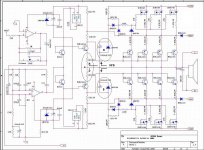
500 w amp
yes the output stage is common emitter, similar to old QSC amps that uses an op amp to drive the output stage, no VAS stage
these is my 1 cent... Junction "A" control the base current of the output trannies with respect from the output of op-amp and "B" controls the +/-HV.
yes the output stage is common emitter, similar to old QSC amps that uses an op amp to drive the output stage, no VAS stage
500 w amp
you are right🙂, i think lm317 has internal protection which limits the driver transistors when the output transistors demands more current drive, just my idea
LM317's are configured as precision current limiter... nice
you are right🙂, i think lm317 has internal protection which limits the driver transistors when the output transistors demands more current drive, just my idea
500 w amp
hmmm... maybe point A in the schematic is the NFB point that connects to speaker output, see all those feedback components from the op amp inverting input, in the schematic point A is connected to psu ground, it might be incorrectly drawn, just my idea, i could be wrong
hmmm... maybe point A in the schematic is the NFB point that connects to speaker output, see all those feedback components from the op amp inverting input, in the schematic point A is connected to psu ground, it might be incorrectly drawn, just my idea, i could be wrong
I think this is a work of luci dog.
Put the link on where you copy.
for more information
creo que eso es un trabajo de luci perro .
pon el link de donde lo copy.
para mas informacion
regards
Put the link on where you copy.
for more information
creo que eso es un trabajo de luci perro .
pon el link de donde lo copy.
para mas informacion
regards
Looks to me like gate drives might be wrongly phased.
High rails enabled only when output doesn't need them.
Maybe I misunderstand how that logic is being driven?
High rails enabled only when output doesn't need them.
Maybe I misunderstand how that logic is being driven?
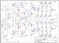
in the schematic the NFB was mistakenly connected to SGND. see attach schematic.
I think the connection you cut was an intentional bootstrap for the op-amps.
here are the complete file with pcb of the output and driver
Get 500-watt-bjt-anfi-devresi-mjl1302-mjl3281.rar on Wupload.com
Get 500-watt-bjt-anfi-devresi-mjl1302-mjl3281.rar on Wupload.com
Hello forum people, am new here, though not new in building amplifiers and other circuits, pls i will appreciate if you could help me with 1000watts amp circuit diagrams.
Has this amp been built and tested? It looks like a nice design.
A 15A transformer in the power supply is going to weigh a TON!
Love to build one of these.
A 15A transformer in the power supply is going to weigh a TON!
Love to build one of these.
Hello i repaired GLS 1800 amp having this kind of circuit i tried to look for NFD but to no avail500 w amp
yes thats it. maybe the feedback resistor is missing in the schematic, there has to be NFB on this circuit somehow, thanks coolet
- Home
- Amplifiers
- Solid State
- 500 watts Class g power amp