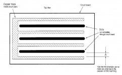
The patent application of Bloodworth and Sanders, found here, describes a method for fabricating electrostatic loudspeaker stators out of copper clad boards (printed circuit board material). One of the features they cite is the "complete encapsulation" of the conductors by the dielectric material. To do this, they use CNC machining to cut slots through the boards, and also cut back the copper trace so that there is a copper-free region between the edge of each trace and the slots that surround it (see figure, extracted from patent application). They then cover the copper traces with another slotted board to complete the encapsulation.
My question is: How important is the gap between the copper trace and the slots? I assume the gap is intended to provide insulation in the plane of the stator, but is that necessary? If not, it seems that a slotted printed circuit board stator could be made without resorting to CNC machining. I'd love to build a CNC router, but spending $2k to build the router is a bit hard to swallow. I can imagine much cheaper, albeit more labor intensive, methods for achieving the same ends as long as the gap between the copper and the slot can be eliminated without running into problems. For example, I have a cheap, plastic tile cutter with a diamond blade that does a great job of cutting PCB material. I can imagine using its blade to cut parallel slots through the boards without resorting to the complexity of a full CNC router.
Thoughts on the importance of the gap between the copper and the slots? The patent application states clearly that one of the main advances they lay claim to is the solution to the problem of insulating the edges of the copper traces, but is that really a big problem?
Few
Attachments
Last edited:
The copper clad problem is a small thickness of the clad - high electrical field intensity at the edge - corona discharge.The patent application of Bloodworth and Sanders, found here, describes a method for fabricating electrostatic loudspeaker stators out of copper clad boards (printed circuit board material). One of the
SKIPPED
Thoughts on the importance of the gap between the copper and the slots? The patent application states clearly that one of the main advances they lay claim to is the solution to the problem of insulating the edges of the copper traces, but is that really a big problem?
Few
That's why edges of the stator shall be round or rounded - it is noted in almost any esl design description.
Cutting the slots would not be the biggest problem. PCB itself with the buried copper layer will be the most expensive part
Besides that inexpensive pcb are usually limited in size - somewhat 18x18 in sq. And price does not come down unless you order hundreds of them..
Alex
P.S. It seems that much easier to make stencil and paint electrodes. Unfortunately that returns us to the root of the problem - insulation layer...
Last edited:
I went to Pad2Pad and drew up a reasonably sized (like 30"x10") PCB that was just the outline of a rectangle (to be used as the spacer, not the stator itself). It was several hundred dollars for each one, and you would need 2 per speaker.
The uniformity would be nice, but this is more of a "professional" part and not something an individual would be able to rationalize.
The uniformity would be nice, but this is more of a "professional" part and not something an individual would be able to rationalize.
I hadn't considered the thickness of the copper clad layer and the resulting electric field strength so thanks for pointing that out.
On the other hand, the cost estimates seem overly pessimistic to me. McMaster-Carr has 24" x 36" single sided copper clad boards for about $29 for 1/16" thickness and $38 for 1/32" thickness.
Boards without the copper cladding (to be used for the insulating layer) cost about $13 for 1/32" x 24" x 36", although that's for a paper and phenolic composite. Fiberglass and epoxy is about $23 for the same dimensions--not sure if you can get away with the cheaper material for the insulating layer.
Either way, four boards of each type would build two 1 foot by 6 foot stators. Considering the flatness of the resulting stators, combined with the ease with which segmentation could be introduced, I find the approach to be an attractive alternative. Of course I have no interest in convincing others that they ought to do it this way--to each his or her own. My original post was aimed at the question of the need for the gap between the copper and the slots. Thanks for helping me think through that aspect. If others have ideas, by all means chime in.
Few
Hi,
i do not see any sense in designing and manufactureing something tricky.
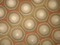
Its Ok just to make a single layer pcb. The copper layer is on the outside, and the copper has a certain distance to the holes. To make it perfect, the copper layer is insulated with coating.
In the picture you can see such a pcb. If you look closer you will recognize, that the copper has some gaps. This enables segmentatioon of the stator.
Capaciti
i do not see any sense in designing and manufactureing something tricky.
Its Ok just to make a single layer pcb. The copper layer is on the outside, and the copper has a certain distance to the holes. To make it perfect, the copper layer is insulated with coating.
In the picture you can see such a pcb. If you look closer you will recognize, that the copper has some gaps. This enables segmentatioon of the stator.
Capaciti
Attachments
i do not see any sense in designing and manufactureing something tricky.
Its Ok just to make a single layer pcb. The copper layer is on the outside, and the copper has a certain distance to the holes. To make it perfect, the copper layer is insulated with coating.
Hello,
Very nice looking stators. Thanks for sharing the pictures.
I did have two questions:
1) Can you share what material you are using for the coating over the copper? I understand you may not wish to share this information for company reasons.
2) Have you noticed any issue with the PCB stators tending to eat away the coating on the diaphragm due to increased corona from sharp edges of the copper? Beveridge describes it like this "...the edge of the thin copper sheet around each hole is like a knife blade. Even where the insulation did not break down, corona forms quickly at the edges around these holes...." He noticed that after years of use, the corona ate away at the coating in circles around the sharp edges of the holes in the copper layer. According to his patent, he used nylon as a coating over top of the copper trace.
Old Beveridge thread:
http://www.diyaudio.com/forums/planars-exotics/51103-harold-beveridge-esls-2.html#post720289
Beveridge PCB stator patent:
Electrode for electrostatic transducer - Google Patent Search
Last edited:
Bolsert,
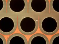
1. The coating is from the german company Peters and is called DLZ 1600. Its a specific coating which builds up to 200 micron in one layer without droping into the holes (as you can see in the picture). Processing this coating is a nightmare. I did it on my own, but if i would have followed up the pcb-stator i certainly would have given this task to a coating specialist. It worked fine, but i cancelled further activities of pcb stator, because still a wire stator easily outperforms any other stator design for most aspects (costs, safety, reliability, easy, efficiency.......)
2. corona is an issue if the copperlayer has sharp edges and you are right, insulation wont help in this case. Therefore you need a certain edging of the copper. There are some pcb manufacturer which are able to edge in such a way , that the copper layer is softly rounded at the edges.
Capaciti
intresting
This is very interesting, quote from "rbrv" along time ago, a way of testing and a differnt idea for an esl, his quote."That's a good question about a reverse esl. I would propose that the first thing to do is to define what constitutes an esl.
The common use and widespread acceptance of the high resistance, constant charge membrane working between two stators is what most people think of as an esl. In these systems the membrane is passive and the stators do all of the work.
If we accept that definition, then a reverse esl would be to have a constant charge on each of the stators and the membrane carrying the audio. This would make the stators passive and the membrane would do all of the work. In that case, the amount of voltage necessary would not change.
In a Beveridge system, there is no passive component. Both the stators and the membrane are active. All three carry the audio. The benefit of this is that it reduces by half the amount of voltage necessary for the same amount of sound pressure. I think that this is still an esl, but certainly is not what most people think of as an esl.
As far as having the aluminum evaporate from the Mylar when used with conventional electrodes, I may be able to shed some light on that.
I have studied the loss of aluminum I found in the transducers my father made with the more conventional circuit board electrodes. I believe you are correct regarding the high charge density, and specifically that it is caused by corona.
Corona is formed at the surface of a conductor carrying high voltage. It still forms even if the conductor is well insulated. On my father's circuit board electrodes, the edge of the thin copper sheet around each hole is like a knife blade. Even where the insulation did not break down, corona forms quickly at the edges around these holes.
In studying the Mylar from at least 50 of these transducers, I have found that the aluminum coating started evaporating in small circles around each hole. In more severe cases, these circles had grown to the point of overlapping each other. In the most severe cases, virtually all of the aluminum coating was completely gone from the entire surface.
I have a highly polished copper pipe which is about one inch in diameter. It has a long wooden handle. I use it in conjunction with a Variac and a neon light transformer to check my electrodes for arcing. This set-up can produce up to 9,000 volts. I place plastic spacers along the sides of an electrode and then I slide this copper pipe back and forth along the spacers. When I do this in a darkened room, I can see the blue light of the corona forming between the electrode and the copper pipe. The more voltage I apply, the brighter the corona.
With the circuit board electrodes, the corona first forms as circles around the holes and other places where there is an edge of the copper sheet underneath the insulation. The corona forms at relatively low voltages at these edges. At higher voltages, this blue circle gets very bright and even develops into a white ring surrounded by blue corona.
When I do the same thing with the Epoxy composite electrodes which we made in the '70's, this corona forms a uniform blue light along the whole surface of the copper pipe. At higher voltages, the blue light is brighter and some white "sparkles" appear as well. With my new electrodes, these "sparkles" still appear, but at much high voltages. With them at extremely high voltages, the lovely blue corona just gets thicker and a brighter blue and is still perfectly uniform.
I have been told that corona is mostly empty space with a few highly charged particles moving very fast. I know that the aluminum coating on the Mylar is only a few atoms thick. It is my guess that every once in a while, one of these high energy particles hits the Mylar and knocks off one or two atoms of aluminum and that this can eventually remove the whole coating. That is what it looks like to me.
Rick Beveridge
i do not mean to intrude on the toppic, but that is very neat and very crrious. Mav
As soon as AC voltge applied with or witout dielectric there will be discharge at some voltage level.
So ionised particles will move out or to the electrode, depending on the sign of the charge.
Electrons are small and does not damage electrode/dielectric.
The latter can't be said about ions. Older ones can recall ion traps in CRT.
Magnetron sputtering would be one of the technologies relevant to the phenomena observed - i.e. coating "disappearence".
Alex
I'm either too stupid or too stubborn to let this idea go without convincing myself it doesn't have merit.
Latest thoughts:
There seem to be several reports of Sanders' pcb-based ESLs producing very high SPLs and he "claims" extremely high reliability. I realize we shouldn't believe everything stated by the manufacturers when they're trying to sell their wares, but if the Sanders panels play loudly and reliably, that would seem to suggest this approach is viable.
Thanks in advance to anyone with the patience to help work through these ideas.
Few
Latest thoughts:
- McMaster-Carr sells 1/32" thick (slightly less than 1 mm for those who prefer more practical units) fiberglass boards with copper cladding on both sides and sells them for a reasonable price. If the stators were made by slotting these boards, and then insulating the side that faces the diaphragm with another fiberglass board with similar thickness, might the double layer of copper reduce the "knife-edge = large electric field" issue? I'm assuming that both copper faces would have the same voltages applied. It seems to me that the sandwich of two copper layers would approximate a 1/32" thick solid copper layer and help avoid the electric field hot spots associated with a single thin layer. Is that wishful thinking?
- Can anyone explain to me why the insulation does not help reduce corona discharge problems at a given voltage? I would think that the dielectric would get polarized by the applied field and reduce the net electric field between the dielectric and the diaphragm (or the other stator). Of course if the intention was to say that you have to crank up the voltage to make up for the losses I just described, then that is another issue. But for a fixed applied voltage, would an insulating dielectric not reduce the corona discharge?
There seem to be several reports of Sanders' pcb-based ESLs producing very high SPLs and he "claims" extremely high reliability. I realize we shouldn't believe everything stated by the manufacturers when they're trying to sell their wares, but if the Sanders panels play loudly and reliably, that would seem to suggest this approach is viable.
Thanks in advance to anyone with the patience to help work through these ideas.
Few
Hi,
other panels do play loud too and are reliable too. Playing loud is a matter of dimensioning to a great deal. There is for example no reason why e.g a metal sheet stator should be inferior to any other stator if the whole wands are deburred and rounded and if the right coating is applied. Featuring a much thicker conductor (besides wire) with greater possible radii, the chance of corona build-up can be lower than with a pcb-stator.
Sander´s patent is just about a different manufacturing procedure. It presents no other improvement but for the manufacturer who can order a stator after his feashion ready to work with from the PCB-manufacturer of his choice. It relieves him from actually ´manufacturing´ a stator himself. A procedure which is common technical standard, but no one cared about a usage for ESLs until Sanders. If ordered in sufficient numbers, the reduction in labour cost will be higher than the material cost. The technique of using PCBs and encapsulating the conductors is not at all a novelty. It is as old as Quad´s and Beveridge´s patents.
jauu
Calvin
Look for solosound they use PCB 4 elements of 10x15 cm have Stijns 90 db efficiency they are crossed at 350 hertz. At least THE solostatic
Hi,
those efficiency values You gave are of no use, as long as the conditions are not known. I seriously doubt that such a small panel reaches a value of 90dB at 350Hz, free in air (open Baffle) with a voltage of 2.83V at 1m distance.
jauu
Calvin
those efficiency values You gave are of no use, as long as the conditions are not known. I seriously doubt that such a small panel reaches a value of 90dB at 350Hz, free in air (open Baffle) with a voltage of 2.83V at 1m distance.
jauu
Calvin
They got à bafle i thinking it Ajax at 1 m distance. Polarisation voltage wha overrijpe high somewhere around 4000-5000
Sorry for overquoting, otherwise the idea will be lost...I'm either too stupid or too stubborn to let this idea go without convincing myself it doesn't have merit.
Latest thoughts:There seem to be several reports of Sanders' pcb-based ESLs producing very high SPLs and he "claims" extremely high reliability. I realize we shouldn't believe everything stated by the manufacturers when they're trying to sell their wares, but if the Sanders panels play loudly and reliably, that would seem to suggest this approach is viable.
- McMaster-Carr sells 1/32" thick (slightly less than 1 mm for those who prefer more practical units) fiberglass boards with copper cladding on both sides and sells them for a reasonable price. If the stators were made by slotting these boards, and then insulating the side that faces the diaphragm with another fiberglass board with similar thickness, might the double layer of copper reduce the "knife-edge = large electric field" issue? I'm assuming that both copper faces would have the same voltages applied. It seems to me that the sandwich of two copper layers would approximate a 1/32" thick solid copper layer and help avoid the electric field hot spots associated with a single thin layer. Is that wishful thinking?
- Can anyone explain to me why the insulation does not help reduce corona discharge problems at a given voltage? I would think that the dielectric would get polarized by the applied field and reduce the net electric field between the dielectric and the diaphragm (or the other stator). Of course if the intention was to say that you have to crank up the voltage to make up for the losses I just described, then that is another issue. But for a fixed applied voltage, would an insulating dielectric not reduce the corona discharge?
Thanks in advance to anyone with the patience to help work through these ideas.
Few
Let's define the "corona". Saint Elmo's fire is a corona discharge. It presumes an exposed (bare) conductor with or without sharp edges, current flows into the air. Same phenoma is used in needle type emitters. Conductor embedded into dielectric will have almost the same field intensity, but no path for current exists. So I doubt the codutor insuide 0.8 mm epoxy impegnated fiberglass will produce CORONA discharge. However the edge of the conductor at question shall be covered with dielectric from all sides and not to be covered by a sheet of insulator. If you get air void you'll get the path for the current. Back to PCB(PWB) stator. With the RV3/4 pattern and insulator thickness 0.8mm all way around conductor in narrow places conductor width tends to be near zero, as shown provided by Calvin.
Second type of discharge is called barrier one. The layer of water (at least that's explained this way) and isolated inductor create the capacitor. If you apply AC voltage to a capacitor, AC current (displacement) will flow. So there will be variable charge at the dielectric surface, and, at some field intensity it will discharge into the air. Since there is no such thing as real puddle of the water on the surface, small isles of water film discharge on at the time, which can be observed on the current waveform. It's a nasty thing due to the fact that the current is much higher of the static (corona) one. Both create ozone and nitrogen dioxide. Again, I doubt that @ 1kV rms and the distance between stators of 2mm or more and presence of 2x0.8=1.6 mm of FR4 one would observe BARRIER discharge.
The cure: equalizing the potential between conductor and the surface of isolator. Here comes Beveridge with semicoductive stators and Calving the Great with black PVC wires...
Alex
P.S. Please correct me if I am wrong, the problem of stacking conductor and a sheet of FR4 is the air gap between the two, creating the path for the current flow (creep).
I do have to note that these solostatics idee really low conductive coating somewhere around 400k and indeed used à cnc to remove the copper clad around THE holes and used spacers of 1 mm. They used an laquar to isolate THE copper clad. Because of THE high polarisation voltage THE where prone to arcing at really high volume or when they where à bit old 20 years or something. So reliable not really well at least for THE arcing part coating still hold bug laquar did not. I Will make some pictures of some elements still got à few.
Let's take, for instance, optocoupler. It does withstand few kV, AC as well. Dielectric barrier is about 2 mil thick. Another example: film capacitor. Conductor thickness is next to zero. No arcing, no corona in properly designed part.I do have to note that these solostatics idee really low conductive coating somewhere around 400k and indeed used à cnc to remove the copper clad around THE holes and used spacers of 1 mm. They used an laquar to isolate THE copper clad. Because of THE high polarisation voltage THE where prone to arcing at really high volume or when they where à bit old 20 years or something. So reliable not really well at least for THE arcing part coating still hold bug laquar did not. I Will make some pictures of some elements still got à few.
Thirdly, conductor in PCB stator is fully surrounded with near perfect (without defects) dielectric. It's hardly acheivable with ordinary paint, enamel, varnish which is usually porous to some degree, especially if no vacuum involved...
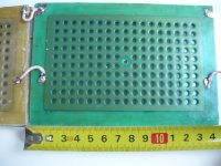
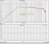
here's a picture. and for the record, the 90 db effciecy is whas statet in a how to make esl's book from fikier a dutch guy who wrote about esl's. but this could be false information ofcourse like the 88dB rated es200 wich does not even get to 85.
maybe i could compare them to my bookshelf speakers ? at 1 m distance they rate 87 or is this not gone work ?
I remmember using 6 of these to mate with a magnepan smg-a wich are 90 db stated by magnepan ofcource. i really had to bring down the voltage of the panels from the 12 diode capacitor step up to the 3rd.
this is measurement of an old solosound panel up close, so its not the same as 1 meter. proximity etc
Attachments
1. Patents have a rhetoric all their own intended for "marketing" to the patent clerks. Very special purposes and often what appears to be the "unique" reason for the patent is trivial to anybody but the clerk.
2. A lot of issues get simpler if you opt for high voltages and big spacing. Like a lot of things today, easier to bring about a fix through electronics than mechanics.
Footnote: yes, you can go nuts with high voltages too. Dayton-Wright has enormous voltages but packed the drivers inside a sealed bag and filled the bag with inert welding gas. Advantages and disadvantages.
Last edited:
- Home
- Loudspeakers
- Planars & Exotics
- question about Sanders' PCB ESL stators