Hi Calvin,
Thanks for the post. I'm certainly aware that there are several ESL panel technologies that can play loudly. It was not my intention to imply otherwise. It also was not my intention to make more of Sanders' claim to originality than is warranted. There have been many commercial ESLs based on PCBs, many of which came out before Sanders'.
For me the question is whether there is a practical way to use copper clad boards to make very flat, easily segmented, and reliably insulated stators that perform well. I've made insulated perforated steel stators, I'm in the (very slow) process of making wire stators. Based on those experiences I'm seeking an approach that offers the best balance of performance, ease of manufacture, and cost.
With McMaster-Carr's copper clad boards I think the materials cost can be fairly low. I also think there might be a way to use a cheap (US$15) diamond blade to cut slots in the board without resorting to CNC. Together, that might make for a reasonably priced way to use copper clad boards.
So that leaves the questions of performance and ease of manufacture. From the posts so far I think it's clear that it's important to fully insulate the conductor, not just cut slots in copper clad boards and leave the edges of the copper cladding exposed.
alexberg: Thanks for the discharge explanations. I found them quite helpful. Am I paraphrasing your point correctly by saying that the corona problem lies in the fact that air is a decent insulator until it starts to break down, at which point lots of current can flow, unless there's a dielectric insulator to resist that current?
In the case of barrier discharge, I'll have to think about whether it might be helpful to make the stator surface hydrophobic. If doing so reduces the adsorption of water, that might help. On the other hand, if water does adsorb to a hydrophobic surface it's more likely bead up and that could aggravate the problem. Hmmm...
My thought was to use slots instead of holes, and to find a way to segment the copper conductor without thinning the edges of the copper or creating very sharp points of the type Capaciti showed in his photos. The reason I raised the option of boards with cladding on both sides, and applying the same voltage to both copper layers, is that I wondered whether doing do would cause the two copper layers to behave like a single thicker layer of copper, less prone to creating regions of localized very high electric fields.
bentoronto: I agree some things get simpler with larger diaphragm-stator spacings, and the higher voltages they require, but other things get more complicated. I'm not sure you come out ahead cranking up the spacing when you take all the factors into account. On the other hand, you need quite precise construction techniques to deal with small spacings. That's part of the reason I started thinking about copper clad boards: they start flat, and they are not easily kinked irreparably by mishandling. Metals are malleable, but once they become non-flat it can be a real pain trying to get them truly flat again.
Thanks, all, for the contributions. I was hoping to come away convinced the diy copper clad board idea is either brilliant or stupid, but as is usually the case, there seems to be some gray area.
Few
Last edited:
Hi,
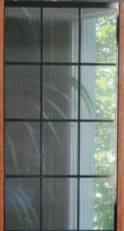
what´s neat about the PCB stator is that You could make 2 sides of different thickness, say 1mm to the (touchable) outside and 0.5mm to the membrane side. This would allow to optimize insulation thickness for each side of the stator. While the dimensional constancy of stator thickness and evenness is sufficiently high for the PCB board itself I´m not sure that this still holds true for the routed PCB stator. At least mechanical stiffness comes down considerably, i.e the punched/routed stator will be flimsy. So You need bracing to increase stiffness. Still though You will never reach the factor of openness that is possible with punched metal sheets of wires. Too You very probabely need to sink the holes so that the holes are of tapered shape instead of a cylindrical to keep the upper bandwidth limit beyond 20kHz.
At last.....it looks ugly.....no beautiful transparent designs.
jauu
Calvin
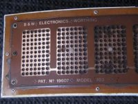
btw: Patent GB1,239,658 issued to B&W in 1971 also deals with PCB-alike stators. Which makes them already three besides Quad and Beveridge.
what´s neat about the PCB stator is that You could make 2 sides of different thickness, say 1mm to the (touchable) outside and 0.5mm to the membrane side. This would allow to optimize insulation thickness for each side of the stator. While the dimensional constancy of stator thickness and evenness is sufficiently high for the PCB board itself I´m not sure that this still holds true for the routed PCB stator. At least mechanical stiffness comes down considerably, i.e the punched/routed stator will be flimsy. So You need bracing to increase stiffness. Still though You will never reach the factor of openness that is possible with punched metal sheets of wires. Too You very probabely need to sink the holes so that the holes are of tapered shape instead of a cylindrical to keep the upper bandwidth limit beyond 20kHz.
At last.....it looks ugly.....no beautiful transparent designs.
jauu
Calvin
btw: Patent GB1,239,658 issued to B&W in 1971 also deals with PCB-alike stators. Which makes them already three besides Quad and Beveridge.
and solosound from the 1970, also Van medevoort had pcb stators, and yes they dont look as good as a nice coated sheet of metal thats for sure. 🙂
Hi Calvin,
SKIPPED
alexberg: Thanks for the discharge explanations. I found them quite helpful. Am I paraphrasing your point correctly by saying that the corona problem lies in the fact that air is a decent insulator until it starts to break down, at which point lots of current can flow, unless there's a dielectric insulator to resist that current?
In the case of barrier discharge, I'll have to think about whether it might be helpful to make the stator surface hydrophobic. If doing so reduces the adsorption of water, that might help. On the other hand, if water does adsorb to a hydrophobic surface it's more likely bead up and that could aggravate the problem. Hmmm...
SKIPPED
Thanks, all, for the contributions. I was hoping to come away convinced the diy copper clad board idea is either brilliant or stupid, but as is usually the case, there seems to be some gray area.
Few
1. Corona discharge relies on avalanche, i.e. there has to be free space for ionized particle to accelerate and, colliding with other partilce create even more charged particles. Removig air voids mitigates this condition.
Solutions:
a) make the radius bigger i.e. deburr the holes in sheet metal,
b) make isolatior more or less perfect.
Without vacuum it's almost impossible to remove air, so, in case of paint make a lot of thin layers instead of single thick one.
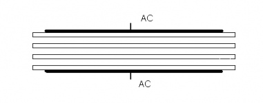
2.Please fo not be misleaded. Pic below shows a part of real discharge device. Isolators and air gaps are 20mils or 0.5mm each.
This yeilds 2 mm of alumina and 1.5mm of air. It takes 3.5kV RMS or 10kV pk-pk @ 5kHz to operate.
Type of dielectric does nor change much. FR4, PTFE glass quartz etc. Alumina is just most durable material.
This gives you a clear indication what AC voltage level in regard to barrier discharge required or the other way around what AC voltage is permissible for a given thickness of air and dielectric.
In regard to hydrofobic properties of fluoropolymers or polyolefines like polyethylene, polypropylene.
I would bet if polarization voltage is applied stators would attract dust unless you seal the whole thing.
Dust covered PTFE surface is no better than any other dielectric...
Alex
FIY PTFE does not melt and made of small particles and is usually porous. That's why isolator in HP optocoulers is impregnated, i.e. no pores.
To Calvin
Tensile strength of FR4 is somewhat lower than one of stainless steel: 48000psi and 75000psi respectively and is pretty close to one of low carbon steel used for perforated sheet, 58000psi. Since fiberglass based material is used for making icebraker hulls it's unlikely that 1 mm FR4 stator would be "flimzyer" on inferior to the steel one. At equal mass FR4 will be more rigid. It's fair to mention that perforated metal is not really flat but contains ark like shapes in cross section, which makes it stiffer.
Now let's define the uglyness factor...😉
Some level of visual transparency is apparently possible for those who value this feature highly. This picture is from Sanders' site:
I like semi-transparent panels, but transparency is not a top priority for me.
I do agree, Calvin, that some care will be required to ensure the slotted PCBs don't lose their flatness. As alexberg points out, though, the board material is pretty tough stuff. I like the fact that it is not prone to getting permanently kinked or bent. The same cannot be said about metals. My first experiments with perforated aluminum were a real pain in that regard.
Thanks for the B&W patent info. I'll take a look. You seem to be trying to convince me that Sanders isn't the first to use this approach, but as I said, I don't need any convincing. I'm well aware of the fact that this idea is not new. Metaxas provides another example of commercial ESLs using copper clad boards. Their site provides a little bit of information---unfortunately terribly new or informative.
Alexberg, did you intend to attach a picture to your post?
Few
I surely did.
If its gonna serve any purpose, it's discharge device
If its gonna serve any purpose, it's discharge device
Attachments
Last edited:
Every one is talking of patents on copper clad PCB stators. Are perforated PCB stators with say 3.5 mm holes patented? I have made a pair of ESLs for my computer sound system with PCBs with 3.5 mm holes and etched and coated with green mask for insultation. I drive it through a bi amplifier with a cross over of about 325 Hz with a bass speaker.
im sure fr4 1mm does not come close to 1 mm steel stifness wise. use both allot, and not at all the same 🙂 fr4 is bendy 🙂 the way they are used in the ESL from sander.. in these tiny slits... im sure you can push them with a finger into major trouble. the wires used in an audiostatic or any other solid coppper wire stator can have the benefit of being stretched along solid rods. making them stiffer then equivalant 1mm pcb in my opinion 🙁 and far better insulated all around. also the touchable side. that does not crack or falls off due to the high voltages. like many solosound panels start becoming troublesome after a while. a while does mean 10-20 years... so stikll rather ok but they will fail in the end !
Last edited:
also the touchable side. that does not crack or falls off due to the high voltages. like many solosound panels start becoming troublesome after a while. a while does mean 10-20 years... so stikll rather ok but they will fail in the end !
The thread mostly derailed into single-layer board designs with insulating coatings, but according to the patent application (not granted last time I looked), the Sanders panels use multi-layer circuit boards with the conductor buried inside the board, so the insulator on both sides should be stable for many, many years. This should give designs of this type significant advantages compared to single-layer boards with or without solder mask, conformal coatings, etc. That doesn't mean it was necessarily patentable, but it does have advantages.
The basics of circuit board stators are covered in pretty old, expired patents, so they are in the public domain now. A typical, simple design should not have any current patent conflicts or inherent patentability.Every one is talking of patents on copper clad PCB stators. Are perforated PCB stators with say 3.5 mm holes patented?
I'm not sure what angle you're asking the question from, but for personal use, even current patent conflicts are not a hindrance. They only matter if you are trying to sell a product or otherwise profit from the design.
Last edited:
Thank you Mattstat for your reply. To answer your question of angle . The sound quality of the ESLs made by me was extremely impressive to many who have seen it and I do get requests to make a few for sale. I was wondering whether I would be infringing on patent rights.
I have an other interesting question on stators profile. Will a tightly stretched copper wire mesh almost (like a silk screen ) mounted on a frame work as stators?
I have an other interesting question on stators profile. Will a tightly stretched copper wire mesh almost (like a silk screen ) mounted on a frame work as stators?
ER Audio is selling a kit with PCB stators. Not sure if they have the conductors buried in an internal PCB layer or not.
ESL IV Kit
Sheldon
ESL IV Kit
Sheldon
Will a tightly stretched copper wire mesh almost (like a silk screen ) mounted on a frame work as stators?
Yes. The common way to do this is to glue aluminum window screen to egg-crate style fluorescent light diffuser. This is the same kind of grid used to hold the wires in Acoustat panels.
At smaller spacings, a window screen based panel will not be as efficient as one that uses perforated metal or closely spaced simple wires though. The weave of the screen prevents a significant portion of the stator from being at the same/minimum spacing. At 0.1" spacing, window screen is about -2 dB compared to 40% open area perforated metal (0.125” holes on 0.1875” staggered centers). At 0.04" spacing it's around 5 dB difference. This may or may not be important to you. A screen with smaller wires should decrease the loss also.
One other thing to be aware of is that insulating screen-based panels can be tricky. Again, this aspect may or may not make much difference to you.
Last edited:
Thanks indeed for the excellent tips. I am planning to order two 12 inch X 14 inch mesh for trials and check how it rates. Thanks
Hi,
are You assuming or can You back up?
From my gut feeling I'also think that FR4 stators are less stiff, but then .... I haven't tried it ... and Alex made a good point.
Wires certainly are nice as You don't need to think much about insulation. It's the same thickness all around.
The Question I have is ... does the degree of insulation required to make the stator outside safe have to touch be the same as the insulation towards the diaphragm?
If we are talking about constant charge ESLs than the voltage between membrane and stator decreases when both approach each other ... becoming null in the event of touch ... theoretical that is.
This would allow for thinner insulation thickness and higher possible efficiency.
jauu
Calvin
are You assuming or can You back up?
. . .
The Question I have is ... does the degree of insulation required to make the stator outside safe have to touch be the same as the insulation towards the diaphragm?
If we are talking about constant charge ESLs than the voltage between membrane and stator decreases when both approach each other ... becoming null in the event of touch ... theoretical that is.
This would allow for thinner insulation thickness and higher possible efficiency.
I'm not completely clear on who or what you are questioning. In case it's me, here are my general responses - some of which may be misinterpretations of your questions:
I've made small prototypes with single-layer FR-4 with a couple different sizes of routed slots. These were run at Beta LAYOUT. The rigidity in a roughly 2 by 4 inch panel seemed adequate for midrange and up, but it's not an immovable mass of infinite rigidity, if that's what you're after. Circuit boards tend to be warped more than you'd think also. Mine flattened out with some persuasion by hand and weighting them down overnight. I didn't exhaustively test these as I was mostly looking at sensitivity and overall feasibility, and the output I was looking for just wasn't there for the size I wanted. I can dig out more of the specifics if you are interested.
Dielectric breakdown on FR-4 is generally stated as greater than 30-50 kV/mm (depending on which spec you are looking at). Dielectric breakdown on PVC is typically stated as 10-30 kV/mm (PVC being what Janszen and Acoustat used with great success). Whatever safety margin you feel like you need in a multi-layer circuit board can likely be dealt with through careful selection of layer thickness, clearance between features, etc. As others have stated, multi-layer boards are not cheap though. As of 2019, at 100 square foot pricing, rough estimates were $0.25/square inch for a 4-layer board (small quantities can be 10x that or more).
As long as the dielectric constant of the insulation is adequate, at practical thicknesses there shouldn't be a large impact on output, so I'm not sure that deserves much worry.
I have no problem with wire stators. I've made them, and I like them for low volume production by a skilled builder. They aren't fast or easy though, especially if you don't have some experience, equipment, and skills. Building an Acoustat-style panel makes things a bit easier, but the cosmetics suffer and there are still a lot of details to handle.
Hi,
it was a reply to Wrinex on #30. Somehow missed there were answers after already.
jauu
Calvin
it was a reply to Wrinex on #30. Somehow missed there were answers after already.
jauu
Calvin
Hi Calvin 🙂 can i back it up >? hihi well i used both 🙂 and 1 mm or 2 mm FR4 is floppy. compared to 1 mm steel. so i cant back it up by any numbers just a finger. but that tells me enough, even without making them toothpick wide slits. even a solid piece of FR4 is far more floppy then a perforrated sheet of 1 mm steel.
SOlosound and audiostatic both used 1.8mm PCB with holes. making slits like sanders , makes rigidness even worse. faaaaar worse. and even those panels are only 15x10 cm and easily bend or pushed out of shape
i would opt for wires over PCB, they can be tensioned and have a rather good insulation all around. and are massively cheapper and easy to segment 🙂 Unless someone wants to make a really weird design or stacked membranes.
Last edited:
- Home
- Loudspeakers
- Planars & Exotics
- question about Sanders' PCB ESL stators