Hello,
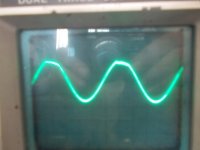
I recently started to build an amp based on the LME49830 with a MOSFET output stage using 2SK1058 and 2SJ162. Everything seems to be working except I get high frequency oscillations (around 400kHz with a magnitude of maybe 200mV) that appear on the the positive output peaks of a sin wave test signal. The amp is running off of a +-45V supply. Of note is that when I disconnect the mains and let the amp run just off of the supply caps the oscillations go away.
I have tried several things to try and make these oscillations go away. The schematic I am using is pretty much identical to the National Semi ref design. I will try and post some photos of the amp board, power supply etc. but in the mean time I was wondering if anyone else has encountered a similar problem?
Any help would be greatly appreciated.
Thanks,
Sam
As your oscillations disappear when the mains is switched off, you might be seeing noise from your rectifiers. Try fitting series RC snubbers across each diode. The optimum values can be determined by experiment but start off with 100R and 10nF - see what happens.
monitor the rectifier/smoothing cap voltages for ripple and oscillation, when you know the amp is reproducing properly and when it is misbehaving.As your oscillations disappear when the mains is switched off, you might be seeing noise from your rectifiers.
Thanks,
I will try adding RC snubbers to the rectifiers. Currently I have 0.1uF caps across them but I will try RC as well. I have monitored the rails and do observe oscillations on both the + and - rails, however oscillations only show up on the positive peak of the output. Recently I did add a RC snubber to the output of the power supply and did notice the oscillations reduced.
I will post my results later today after I make the changes.
does the rail behaviour change with the output misbehaviour?I have monitored the rails and do observe oscillations on both the + and - rails, however oscillations only show up on the positive peak of the output. Recently I did add a RC snubber to the output of the power supply and did notice the oscillations reduced.
Andrew,
I went back to look how the rails behave. They show the same pattern of oscillation, that is, they only oscillate when the amp output is at its most positive point.
When the output from the amp is increased the oscillations on both the amp output and supply rails are reduced both in duration and magnitude. This has me very puzzled. It appears that as more load is placed on the power supply it tends to have less oscillations.
Later today or tomorrow I will try to add RC snubbers to the rectifiers and post back.
Last edited:
I think what you are confirming is that the power amp kickstarts a potentially unstable PSU system when the PSU does not like a fast transient demand for current.
It's that potentially unstable PSU system that needs sorting.
However, this may be made worse by applying amp decoupling in the wrong places/values.
It's that potentially unstable PSU system that needs sorting.
However, this may be made worse by applying amp decoupling in the wrong places/values.
It could be the amp that's unstable reflecting back into the PSU.
Is your layout good, with correct grounding and feedback returns used ? Short low impedance paths to the FET's ? Any zobel network correctly returned ? Gate stopper resistors mounted as close to FET's as possible ?
Might be worth adding a small (0.1uf) from each FET supply (drain or source depending on configuration) to PSU ground.
Hello,
I recently started to build an amp based on the LME49830 with a MOSFET output stage using 2SK1058 and 2SJ162. Everything seems to be working except I get high frequency oscillations (around 400kHz with a magnitude of maybe 200mV) that appear on the the positive output peaks of a sin wave test signal. The amp is running off of a +-45V supply. Of note is that when I disconnect the mains and let the amp run just off of the supply caps the oscillations go away.
I have tried several things to try and make these oscillations go away. The schematic I am using is pretty much identical to the National Semi ref design. I will try and post some photos of the amp board, power supply etc. but in the mean time I was wondering if anyone else has encountered a similar problem?
Any help would be greatly appreciated.
Thanks,
Sam
Just a thought,
Can't it the amplifier get unstable above a certain rail voltage? If you disconnect the mains, the voltage get lower and slide down.
The best way to find this out is, use a variac. And start at a low voltage operating point while you montor the sine wave in a load. Raise the voltage and see if the sine wave change. Big chance above a certain threshold you see the oscillation kicks in.
I had it too in one of my designs. Everything worked great till +/- 35 VDC. But going higher I got oscillations. A change of miller capacitor value and some capacitance from Collector to base on the driver transistors solved my problem.
With kind regards,
Bas
I have tried several things to try and make these oscillations go away. The schematic I am using is pretty much identical to the National Semi ref design. I will try and post some photos of the amp board, power supply etc. but in the mean time I was wondering if anyone else has encountered a similar problem?
Try using a somewhat larger Ccomp -- I don't think that Troy never got around to writing the application note describing the care and feeding of this cap. The demo board design uses IRFP240/9240 which is a lot different from the lateral 2SK1058/J162.
Take a look at the other piece he wrote: Application Note AN-1645 "LM4702 driving a MOSFET output stage"
As mentioned, the gate stopper resistor should be mounted as close as possible to the gate of the output devices. Sometimes the N and P channels will benefit from different values of this resistor.
I went back and added some RC snubbers across the rectifier diodes. This unfortunately did not have any significant impact on the oscillations.
Next I went and looked again at the gate stopper resistors and lowered their value. With this change all the oscillations are gone. I've been testing it most of the day, running all signals, min volume to max volume and no oscillations.
Thanks everyone for the suggestions. I will post more results as I do more tests.
Little old here but I have the same problem with the hybrid with 2sk1058 and 2sj162.
What helps for me is put a small cap 220p between gate and source of the 2sk1058 alone, and i get rid of all oscilations, did not try lowering the resistors
this problem I did now al some years..
It starts oscilating when go higher then 6 volts output with speaker connected (give some induction).
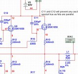
It is known about this problem because of differencies capacity between the fets. use as high capacity as needed, I have now use 47pF each fet, 220 pF is to high, limitting bandwith for hybride..
regards
kees
What helps for me is put a small cap 220p between gate and source of the 2sk1058 alone, and i get rid of all oscilations, did not try lowering the resistors
this problem I did now al some years..
It starts oscilating when go higher then 6 volts output with speaker connected (give some induction).
It is known about this problem because of differencies capacity between the fets. use as high capacity as needed, I have now use 47pF each fet, 220 pF is to high, limitting bandwith for hybride..
regards
kees
Attachments
Last edited:
Well I did try it with the resistors, for hybrid don,t work, I have use a cap on gate to source of the 2sk1058 this did solved always all that years, also elector did this.
I have dome a 33 pF cap, just try it how much you need, less capacity is alway better.
I have dome a 33 pF cap, just try it how much you need, less capacity is alway better.
What helps for me is put a small cap 220p between gate and source of the 2sk1058 alone, and i get rid of all oscilations, did not try lowering the resistors
this problem I did now al some years..
Did you try changing the value of Ccomp first?
Try this test -- feed the amp with a 10kHz square wave for about 1/10th rated output and see if there is ringing. If there's a problem increase Ccomp.
The slew rate of the amplifier is going to change with output voltage, so you can keep raising the output power and changing Ccomp until you observe no ringing.
You don't want such a large value of Ccomp that you overdamp the response of the amplifier.
You might also want to reduce the value of the gate stoppers. As Troy wrote in his note, the P and N channel have different gate capacitance so another trick to optimizing is adjusting the value of the resistor for best slew rate.
FWIW, the TI model for the LME49830 is not particularly helpful in guessing the correct value of Ccomp.
Hi jackinnj
I have no Ccomp, because i have a self designed hybrid amplifier, dc coupled tube driver to mosfets, I say this because I have no feedback, the little C between source and gate of 2sk1058 did always the trick for me, but I wil try soon what I gain when correct the capacity between the two. because of the tube driver who has idle of 20 mA the trick with a square wave wil not work, tube drives is a cathode follower so low impedance.
If I have a C comp the things get more easy for remove ringing, I did this a while ago with a C trimmer and then measure and place the cap.
regards
kees
Attachments
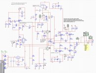
I have no Ccomp, because i have a self designed hybrid amplifier, dc coupled tube driver to mosfets,
I thought the thread dealt with the LME49830.
Yes it did, for a part, because it deal with 2sk1058 and 2sj162 oscillations. and this I had also so i did react on this old thread.
regards
regards
Well a single little cap (22pF styro no ceramic) between drain and gate of the 2sk1058 cure all oscillations.
The same can be reached with gate resistors close to the case of mosfet of sudden value.
Caps are easy ones, it make the amp stable whatever there is on the output like loudspeaker filters.
The same can be reached with gate resistors close to the case of mosfet of sudden value.
Caps are easy ones, it make the amp stable whatever there is on the output like loudspeaker filters.
Little old here but I have the same problem with the hybrid with 2sk1058 and 2sj162.
What helps for me is put a small cap 220p between gate and source of the 2sk1058 alone, and i get rid of all oscilations, did not try lowering the resistors
this problem I did now al some years..
It starts oscilating when go higher then 6 volts output with speaker connected (give some induction).
It is known about this problem because of differencies capacity between the fets. use as high capacity as needed, I have now use 47pF each fet, 220 pF is to high, limitting bandwith for hybride..
regards
kees
Hehehe no it is not 220pF but 22 pF, that is a error in the schematic, cap needs as high to prevent oscillating, even 15 pF or 10pF if it works is enough.
regards
kees
- Status
- Not open for further replies.
- Home
- Amplifiers
- Chip Amps
- LME49830 with 2SK1058/2SJ162 output stage