The caps should be two, between each supply pin and ground. 0.1uF or so close to the terminals and maybe some 100-200uF close by.
I liked the JRC2068, but still the LM4562 sounded better.
I liked the JRC2068, but still the LM4562 sounded better.
Attachments

Last edited:
What happens if I connect only between + and -? I think there is no difference.
How are the JRC2068? Try to describe them.
Do you sell the JRC2068? They are hard to find today.
Ok, the mailing route would be too long. So I look for it here in Europe.
How are the JRC2068? Try to describe them.
Do you sell the JRC2068? They are hard to find today.
Ok, the mailing route would be too long. So I look for it here in Europe.
What happens if I connect only between + and -? I think there is no difference.
How are the JRC2068? Try to describe them.
Do you sell the JRC2068? They are hard to find today.
Ok, the mailing route would be too long. So I look for it here in Europe.
The idea of decoupling caps is to provide a low impedance path at high frequencies to ground and thus it removes the high frequency hash from the supply lines.
The PSRR of opamps is high at low frequencies, but not so hot as frequency increases, which is why they are needed, especially in high bandwidth devices.
@5th element
I know that these caps make the power supply fast, that is why Kenwood already installed 0,1 uF there.
You haven't really said what happens if i only connect supply pin + and - with one cap?
Wouldn't this cap hold power for the opamp?
Could you illustrate this?
I know that these caps make the power supply fast, that is why Kenwood already installed 0,1 uF there.
You haven't really said what happens if i only connect supply pin + and - with one cap?
Wouldn't this cap hold power for the opamp?
Could you illustrate this?
Since at ANY given time, only ONE of the power lines it is used to feed the output in refference to the ground (they alternate because of the push-pull nature of the output stage), your cap won't do nothing to decouple the curent from the lines.
Talk of "fast" power supplies is audiophile gobbledygook, as is trying to assign something like soundstage to a particular part. Think impedance over a frequency range. FWIW, I think opamp choice for filters is one of the most critical applications because impedances vary widely- they have to if it's going to be a filter. Fundamentals have to be right (layout and bypassing) and test equipment is essential to avoid random and inconclusive parts swapping. Some opamps make vastly better filter circuits than others. Though there are entire books on filter design, and books covering layout and such, the information never seems to get together in the same place at the same time.
needless to say ,the transistor output stage intodruces additional phaseshift into the feedback loop. Blindfold parts swap isn't recommended and before blaming opamps for their intrinsic sound, correct circuit operation should be verified by measurement.
regards
regards
Even if you make them work stable with margin high enough, they sound very different. Opamps are best avoided 😉
@ SoNic_real_one
I think that isn't totally correct.
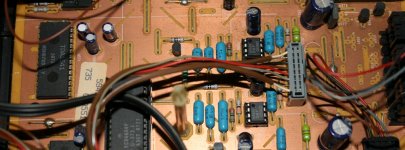
Please look at the schematic: http://www.file-upload.net/download-2761113/DP1001_SM_KENWOOD_EN.pdf.html
There is already as default an additional small film cap at the opamps.
Page 10 row 5 column AF there you see C27 between supply pins + - of opamp IC2 !!
Page 11 on the top left near the off going from pcb there you can see C98 also between supply pins + - of the opamp IC1 !!
Can you tell why there the caps are between opamp suplly pin + and -, and the the big supply caps are connected each to the ground?
Sorry I am a newbie. But thats interesting.
@ Conrad Hoffman
Fast caps in the sense of being able to reload and deliver power for high frequencies that logically going along in low impedance at high frequencies of the supply. It is all the same from a different point of view. I think.
I don't want to offend anybody. I know the silly audiophil people. 😉
@ Juergen Knoop
I don't think that this phaseshift has any effect on a different opamp.
And yes measurement would be the best. 😉
I think that isn't totally correct.
Please look at the schematic: http://www.file-upload.net/download-2761113/DP1001_SM_KENWOOD_EN.pdf.html
There is already as default an additional small film cap at the opamps.
Page 10 row 5 column AF there you see C27 between supply pins + - of opamp IC2 !!
Page 11 on the top left near the off going from pcb there you can see C98 also between supply pins + - of the opamp IC1 !!
Can you tell why there the caps are between opamp suplly pin + and -, and the the big supply caps are connected each to the ground?
Sorry I am a newbie. But thats interesting.
@ Conrad Hoffman
Fast caps in the sense of being able to reload and deliver power for high frequencies that logically going along in low impedance at high frequencies of the supply. It is all the same from a different point of view. I think.
I don't want to offend anybody. I know the silly audiophil people. 😉
@ Juergen Knoop
I don't think that this phaseshift has any effect on a different opamp.
And yes measurement would be the best. 😉
Addition
@ Conrad Hoffman
The impedance of opamps is not important for active filters!
It is only important for current and voltage noise!
@ Conrad Hoffman
The impedance of opamps is not important for active filters!
It is only important for current and voltage noise!
No the point I was making is that for that caps to work as proper decouplers, they have to be connected to ground so the high frequency crap can go there.
Connecting a cap across the supply pins can offer a lower impedance path for small transients in current demand, but in a properly designed PCB they shouldn't really be needed.
If there's more to it then that, someone feel free to correct me.
Connecting a cap across the supply pins can offer a lower impedance path for small transients in current demand, but in a properly designed PCB they shouldn't really be needed.
If there's more to it then that, someone feel free to correct me.
Impedance of the power supply is what I was referring to, but IMO output impedance of opamps is also important. Be careful about taking LF parameters as similar for HF- as 5th element says, for example, PS rejection is usually terrible at HF, in spite of splendid LF numbers.
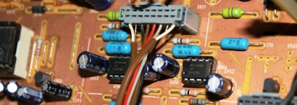
In the manual on page 10:
In the signal path at the audio output at the RCA jacks there are caps connected to ground for cancelling the HF in the signal!
In the power supply there are only the big caps connected to ground. After that there are circuits called "AVR", they are "gyrators" , electronical inductors to smooth or cancel ripple. So there is no need for further HF cancelling in the power supply.
It is not clear.
What do you mean HF crap in the signal path or in the supply path?
What do you mean HF crap in the signal path or in the supply path?
Last edited:
Because those OpAmps don't have the load to the ground like a regular OpAmp, they have suplementary output stages.@ SoNic_real_one
There is already as default an additional small film cap at the opamps.
Page 10 row 5 column AF there you see C27 between supply pins + - of opamp IC2 !!
So the current path goes from positive, via internal transitor of the OpAmp, then to the opposite output transistor an the negative rail that works at 180 degree phase. You basically have TWO separate loads, each to the opposite power rail. That's where you need the decoupling done.
The cap is NOT for the OpAmp but for the whole circuit, OpAmp PLUS output stage (that is also the OpAmp load). Your question was general and in general, OpAmps don't have loads to the opposite rail, but to the ground. In your case, load goes to other rail, cap should go there too.
First stage after DAC thou, I don't think it is right - it needs some caps between supply pins and ground since that OpAmp load is connected to the ground (the next filter stage).
Last edited:
@ SoNic_real_one
Thanks you for these informations.
I only want to try a better opamp from NJM/JRC.
Here is an older overview of opamps for audio from NJM/JRC:Can someone japanese?

I think the NJM4580 and the NJ2068 is worth a try.
Otherwise the NJM4565 is put again in the player.
Thanks you for these informations.
I only want to try a better opamp from NJM/JRC.
Here is an older overview of opamps for audio from NJM/JRC:Can someone japanese?
I think the NJM4580 and the NJ2068 is worth a try.
Otherwise the NJM4565 is put again in the player.
Attachments
Why japanese? They have english page (for characteristics):
Products list[Semiconductor Selection Guides[New Japan Radio]]
As I said, i did try 2068 and where OK, better than original LM833. Denon and Harman Kardon use 2068 as higher end OpAmp in their products.
Personally, I stayed with LM4562.
Products list[Semiconductor Selection Guides[New Japan Radio]]
As I said, i did try 2068 and where OK, better than original LM833. Denon and Harman Kardon use 2068 as higher end OpAmp in their products.
Personally, I stayed with LM4562.
Last edited:
An externally hosted image should be here but it was not working when we last tested it.
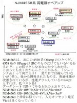
The text below roughly says:
NJM4565 is one of JRC's 4558 series of OPamp. There are many in JRC's 4558 series of OPamp and you can use this chart to slightly understand what type of product they are. There might still be something that you may not understand. What is "shrunken product"? Not visually shrunken in size (laugh). It was developed more recently, did it get better performance compared to the previous product, or was there a reduction in performance, low cost product?
According to the datasheet,
NJM4560: GB=10MHz, SR=4V/uS, Vio<6mV
NJM4565: GB=10MHz, SR=4V/uS, Vio<3mV
Very similar to NJM4565, better input voltage offset Vio!
I think product shrink refers to die shrink.
Last edited:
- Status
- Not open for further replies.
- Home
- Source & Line
- Digital Source
- Opamp change Now some Disappointments