I have searched the forums for this much debated topic but I can not find an answer to my simple question..
What is the vertical dispersion of my planar (NEO8-PDR) ??
I know that it is little, but I find it hard to believe that a soundbeam stays within the 15 cm (6 inch) height for several meters. There must be some dispersion.
The second question is then: Is the vertical dispersion very frequency dependent?
The reason I am asking is that I am going to use NEO8-PDR in my centre speaker together with a 6.5" woofer. My sofa is 4 meters (13 ft) from the speaker and I want to have the option of moving my head a little more that 15 cm (6 inches) without missing out on the dialogue in the movie...
I have more drivers, so another option is maybe to use two drivers in a line and mount the woofer beside them.. (this is a centre speaker)
Armand
Wellif ur ribbon is narow and tall ? if so, the smaller it is the better the dispersion. in this case horzontal. if the ribbon whas wider then tall the vertical dispersion would be better. so a little dot or square would have in both ways the same dispersion. and its all ferquency depended. the higher the fequency the narrower you ribbon need to be to have the best dispersion.
I have searched the forums for this much debated topic but I can not find an answer to my simple question..
What is the vertical dispersion of my planar (NEO8-PDR) ??
I know that it is little, but I find it hard to believe that a soundbeam stays within the 15 cm (6 inch) height for several meters. There must be some dispersion.
The second question is then: Is the vertical dispersion very frequency dependent?
Hello Armand,
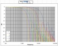
Dispersion is frequency dependent and can be estimated by the sinc function:
sinc[ (pi*f*W)/c * sin(theta) ] = sin[ (pi*f*W)/c * sin(theta) ] / [ (pi*f*W)/c * sin(theta) ]
where:
f = frequency
W= width of sound source (m)
c = speed of sound = 340 (m/s)
theta = listening angle
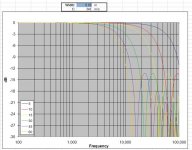
As you can see a 6" wide sound source is pretty directional,losing the top octave at just 5 degrees off axis. This is pretty close to the 6" @ 2m you mentioned.
For comparison, the 2nd plot shows calculated dispersion for width of a typical dome tweeter.
Attachments
dispersion
try to visualize the acoustic lens. You can calculate a lens, a combined for vertical plane and horizontal plane
try to visualize the acoustic lens. You can calculate a lens, a combined for vertical plane and horizontal plane
Last edited:
Hello twest820,
Thanks for posting the measurements. Do you happen to have the file for the Neo8 on the long axis? You seem to have two files posted for the Neo3 long axis, but none for the Neo8 long axis.
Thanks for posting the measurements. Do you happen to have the file for the Neo8 on the long axis? You seem to have two files posted for the Neo3 long axis, but none for the Neo8 long axis.
Thanks!Fixed.
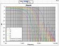
I took your data for the Neo8 on the long axis and normalized the 15 degree and 30 degree curves relative to the on axis data and plotted it up against the theoretical predictions from post #3.
Plot 1) Compares the measured data vs the predictions from post #3 for a 6" wide radiator in an infinite baffle.
Pretty good agreement, but you can see that the measurements were not infinite baffle as the overall level drops as you get further off axis.
Plot 2) Compares the measured data vs the predictions for a 6" wide dipole radiator
Adding in the Cos(theta) SPL reduction with angle off axis for a dipole radiator and we get even better agreement.
Plot 3) Compares the measured data vs the predictions for a 6.25" wide dipole radiator
I'm not sure what the exact dimensions of the Neo8 diaphragm are, but adding 0.25" to the width of the radiator provides a near perfect match with your measurements.
I'd say theoretical directivity calculations come pretty close to reality 🙂
Attachments

Last edited:
Don't think so. What you've determined is Edge's FEM simulation of the Neo8's free air response (no baffle or box) results in agreement with the sinc approximation if you tinker around with the input data. Statistically speaking, the OP's probably using closed box and hence won't see the dipole roll off but will see the ususal directivity reduction from diffraction off the box face. As a reminder, free air is usually a best case for dispersion.I'd say theoretical directivity calculations come pretty close to reality 🙂
I'm not spotting the thread where I originally posted the attachments in this post, but they're a few other models of the Neo3's free air horizontal dispersion after conversion to dipole operation. Opinions varied as to which best approximated Neo3 measurements but, while they're all in the right direction, none is particularly exact. As I mentioned previously, I'm not aware of any Neo8 polar measurements, but I would expect Neo8 simulations to be of comparable accuracy.
Attachments
Last edited:
Don't think so. What you've determined is Edge's FEM simulation can results in agreement with the sinc approximation.
How embarrassing 🙁
I thought the data you posted was actual measurements...I see now that you stated it was simulation results.
Hope I didn't confuse anybody.
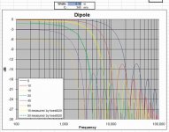
BG8 directivity for long axis, measurements vs theory
Me being me, just couldn't leave things hanging like that.
So I borrowed a BG8 from a friend and took a quick set of measurements to compare with the calculated theoretical off axis response.
Measurements were taken at 1m from the BG8 mounted in free air on a pole attached to rotating platform.
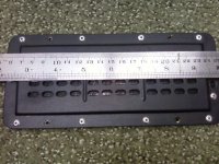
I estimate the width to be about 5 15/16" = 0.1508 m.
Theoretical response calculated using the sinc function mentioned in post#3, and the cos(theta) response for a dipole radiator.
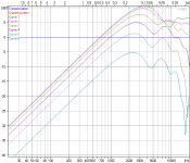
Plot #1
The measured off axis response for the BG8 on the long axis.
Note that I didn't bother to notch out the cavity resonance.
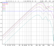
Plot #2
Same data set, just normalized to the on axis response.
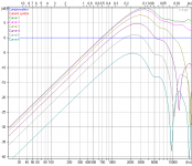
Plot #3
Normalized measurements compared to theory for 5, 10, & 15 degrees off axis.
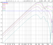
Plot #4
Normalized measurements compared to theory for 30, 45, & 60 degrees off axis.
NOTE: Due to length of measurement window, ignore measured data below about 350Hz.
I thought the data you posted was actual measurements...I see now that you stated it was simulation results.
Me being me, just couldn't leave things hanging like that.
So I borrowed a BG8 from a friend and took a quick set of measurements to compare with the calculated theoretical off axis response.
Measurements were taken at 1m from the BG8 mounted in free air on a pole attached to rotating platform.
I estimate the width to be about 5 15/16" = 0.1508 m.
Theoretical response calculated using the sinc function mentioned in post#3, and the cos(theta) response for a dipole radiator.
Plot #1
The measured off axis response for the BG8 on the long axis.
Note that I didn't bother to notch out the cavity resonance.
Plot #2
Same data set, just normalized to the on axis response.
Plot #3
Normalized measurements compared to theory for 5, 10, & 15 degrees off axis.
Plot #4
Normalized measurements compared to theory for 30, 45, & 60 degrees off axis.
NOTE: Due to length of measurement window, ignore measured data below about 350Hz.
Attachments


Sweet! That's excellent agreement to the first null. 🙂
Did you happen to measure distortion as well? So far as I know, if anyone's taken data to assess how much dipole compensation the Neo8 can handle it's not posted anywhere. But since the dipole "peak" is at 2kHz establishing how low the Neo8 can run due to excursion and Fs limitations is pretty important for assessing its use as a dipole mid. Assuming the Neo8 behaves like the Neo3 and Neo10, Fs is right around 400Hz and the intrinsic distortion should be OK about the same frequency. However, my experience with the Neo3 is equalizing it flat below 2kHz exhausts its excursion capabilites fairly quickly. Since the Neo8's essentially a line array of Neo3s I'd expect similar problems to crop up.
Did you happen to measure distortion as well? So far as I know, if anyone's taken data to assess how much dipole compensation the Neo8 can handle it's not posted anywhere. But since the dipole "peak" is at 2kHz establishing how low the Neo8 can run due to excursion and Fs limitations is pretty important for assessing its use as a dipole mid. Assuming the Neo8 behaves like the Neo3 and Neo10, Fs is right around 400Hz and the intrinsic distortion should be OK about the same frequency. However, my experience with the Neo3 is equalizing it flat below 2kHz exhausts its excursion capabilites fairly quickly. Since the Neo8's essentially a line array of Neo3s I'd expect similar problems to crop up.
Last edited:
twest820. re post #9
What software are you using for the fem plots. Haven't seen this before.
TIA
Iain.
What software are you using for the fem plots. Haven't seen this before.
TIA
Iain.
Note too shabby as a first cut approximation of dispersion, which was what Armand, the OP, was after.Sweet! That's excellent agreement to the first null. 🙂
Did you happen to measure distortion as well? So far as I know, if anyone's taken data to assess how much dipole compensation the Neo8 can handle it's not posted anywhere. But since the dipole "peak" is at 2kHz establishing how low the Neo8 can run due to excursion and Fs limitations is pretty important for assessing its use as a dipole mid. Assuming the Neo8 behaves like the Neo3 and Neo10, Fs is right around 400Hz and the intrinsic distortion should be OK about the same frequency. However, my experience with the Neo3 is equalizing it flat below 2kHz exhausts its excursion capabilites fairly quickly. Since the Neo8's essentially a line array of Neo3s I'd expect similar problems to crop up.
I didn't measure the distortion, but had many years ago.
If memory serves, with reasonable input level 3rd order distortion rose dramatically below 500Hz rising past 10% by resonance.
It wasn't very pleasant to listen to test tones.
Oh, and Fs was about 300Hz I believe, with Q of roughly 2.
Dipole or closed box operation?If memory serves, with reasonable input level 3rd order distortion rose dramatically below 500Hz rising past 10% by resonance.
Thanks. That's with the SPL equalized flat, I assume?
All measurements were performed with constant voltage/frequency input, no EQ applied.
That makes a bit more sense. I'll stick to my guesstimate that once equalized for dipole roll off the Neo8 wouldn't cross happily below 1.1kHz or so when operated nude. 🙂 Appreciate the confirmation I should probably be looking at a cone mid for the nude dipole build I have going.
- Status
- Not open for further replies.
- Home
- Loudspeakers
- Planars & Exotics
- Vertical dispersion on planars. How much?