Phono/Regulator PCB
Hi Quanghao,
Address etc already sent via private mail.
Regards
John Caswell
Hi Quanghao,
Address etc already sent via private mail.
Regards
John Caswell
Hello Quang Hao,Hello!
The PCB is you do not get me very sad thing, and I'll send for you again. PCB hopes will hand to you, no destination Most PCB is not your phone number. I work with prestige, not profit. If you move to make sure, faster, and make sure to place it very expensive.
I've used
You did not get the PCB address please send me an e-mail with the following information:
Name:
Address:
Phone:
Nick DIY:
PCB name:
Extremely thank
I think it would be a good idea give the people the posted/tracking number of the letters, I don´t know how the post system works in other countries,
here in Brazil I can see exactly the ariving and way of your letters in Brazil, but only after receiving the letter when I saw the number on it🙁.
Sometimes have a delay in the customs or goes a wrong way, when you can see it post tracking system you have time to speak with the post.
Klaus
Hi klaju1955 !
Yes that is fine, some country can check it!
Tomorrow i can sent it! Thanks
Thank you Quang Hao,
not for me, I have allready received the set, perhaps it helps John or others who did not received till now.
But in the future I think is good you send to everyone per Email the package number.
Klaus
Hello!
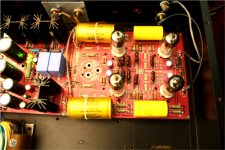
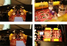
After I finished 4 phono, my favorite is the sound of it, so Andrea has recalculated the values in the circuit. I was very interested in these calculations. Motherboard I do for you called a phono ASH.
Today, I use 50 ohm resistors cadoc for cathode tube D3A , and 0.68 UF capacitor output Jensen. Sounds great.
I had a chance to compare with the EAR 834 phono
Phono D3A (ASH) te sound is better 834,
and I like D3A phono in the following points:
The sound, balanced, very high resolution, Nature
No noise,
Probably due to light interference is very small electronic D3A
SO it is very good Phono.
Attachments
The next week i will ship agian PCB Phono To you
You did not get the PCB address please send me an e-mail with the following information:
Name:
Address:
Phone:
Nick DIY:
PCB name:
Phono D3A PCBs not arrived :
1. johngalt47
2. 2. vanofmonks
3. John Caswell
4. alex1946audio
5. Torsken
......
Any more, Can tell me please!
Thank!
You did not get the PCB address please send me an e-mail with the following information:
Name:
Address:
Phone:
Nick DIY:
PCB name:
Phono D3A PCBs not arrived :
1. johngalt47
2. 2. vanofmonks
3. John Caswell
4. alex1946audio
5. Torsken
......
Any more, Can tell me please!
Thank!
All i still need before the power supply test is my 120k 2W resistor.
I also need better screws for the heat sinks and i need to put in isolating washers so that the heat sinks are not live.
After the power supply is tested i will connect it to the phono part and test. YAY!! 🙂
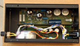
I decided to mount my large capacitors underneath so when i design my enclosure i can easily make my tubes protrude at the top for a classic look. On too Autocad!!
I also need better screws for the heat sinks and i need to put in isolating washers so that the heat sinks are not live.
After the power supply is tested i will connect it to the phono part and test. YAY!! 🙂
I decided to mount my large capacitors underneath so when i design my enclosure i can easily make my tubes protrude at the top for a classic look. On too Autocad!!
Attachments
![IMG_6963 [640x480].JPG](/community/data/attachments/186/186449-85c3bccff380ec708e937f31ac9ba1c9.jpg?hash=hcO8z_OA7H)
![IMG_6965 [640x480].JPG](/community/data/attachments/186/186456-911db138fb54dc5409810168343869c4.jpg?hash=kR2xOPtU3F)
All i still need before the power supply test is my 120k 2W resistor.
I also need better screws for the heat sinks and i need to put in isolating washers so that the heat sinks are not live.
After the power supply is tested i will connect it to the phono part and test. YAY!! 🙂
I decided to mount my large capacitors underneath so when i design my enclosure i can easily make my tubes protrude at the top for a classic look. On too Autocad!!
Hi Tang,
It goes looking fine, I´m also was thinking to make a cabriolet version and perhaps separate the power part in another chassis.
But I´m just looking around for buying the parts, where do you bought yours, in a thread you told for making a list?
Klaus
Here is my Bill of materials so far.
I bought all the "funny" parts from rs components. The rest of the "standard" parts you can find very easily at any electronics shop.
Some parts have the RS part number that I used next to it.
I have added notes with the errors i have found so far.
PLEASE NOTE:
I used the original RIAA circuit with 33nF and 100nF I DID NOT USE THE EXPENSIVE silver mica riaa circuit. You will have to change the RIAA resistors and capacitors too your needs.
I have not tested my setup. Only finished soldering last night. I will test within this week.
Good luck
Tang
Attachments
There is probably still mistakes with my bill of materials.
please let me know if you found any and then i will fix it and update
please let me know if you found any and then i will fix it and update
Hi quanghao
How hot does your irf9610 heatsink get?
The heatsink you prescribed is 8c/w
The heatsink I used is 6.8c/w
When I power it up I set the voltages correctly but the heat sink gets VERY hot i can't Touch it with my finger too long. Is this normal?
How hot does your irf9610 heatsink get?
The heatsink you prescribed is 8c/w
The heatsink I used is 6.8c/w
When I power it up I set the voltages correctly but the heat sink gets VERY hot i can't Touch it with my finger too long. Is this normal?
Hi quanghao
How hot does your irf9610 heatsink get?
The heatsink you prescribed is 8c/w
The heatsink I used is 6.8c/w
When I power it up I set the voltages correctly but the heat sink gets VERY hot i can't Touch it with my finger too long. Is this normal?
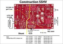
Hi! how voltage between R1?? R1 = 33 ohm??
I'm sure V across 9610 is very big??
About max 30V .now you can change R11, is bigger 200R to 470R or 1K, and 10W.
It is mean:
Attachments
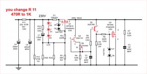
voltage across R1 = 2.3V
AC voltage is 238V
DC voltage 285v Dc this is measured across C5
R11 is currently 220R
I think i will make R11 1K an see what happens.
all my measurements are with no load connected and only power supply plugged in.
Thanks!!
AC voltage is 238V
DC voltage 285v Dc this is measured across C5
R11 is currently 220R
I think i will make R11 1K an see what happens.
all my measurements are with no load connected and only power supply plugged in.
Thanks!!
Last edited:
To get the max performances is necessary to use the new riaa and the new interstage caps.
It is possible use the old value but the expensive silver mica and Jensen caps give another sound.
If you use the new value the result will be near to hi-end Audionote products (7000-10000$ value).
I suggest the old values only if you have normal amplifiers, not hi-end vacuum tubes.
It is possible use the old value but the expensive silver mica and Jensen caps give another sound.
If you use the new value the result will be near to hi-end Audionote products (7000-10000$ value).
I suggest the old values only if you have normal amplifiers, not hi-end vacuum tubes.
Hi AndreaTo get the max performances is necessary to use the new riaa and the new interstage caps.
It is possible use the old value but the expensive silver mica and Jensen caps give another sound.
If you use the new value the result will be near to hi-end Audionote products (7000-10000$ value).
I suggest the old values only if you have normal amplifiers, not hi-end vacuum tubes.
What makes the difference? The values or the cap material?
If I use the old values 100nF/33nF und put silver mica, the new value with silver mica will sound better?
There are russian silver mica SS3, the can go to this old value, you have experience with them?
I know that the quality of the coopling caps has a great influence.
What is about the resistors in the filter circuit, it´s better to use tantal R?
Klaus
the cap materials make the difference, both values are good
The mica and Jensen are very expensive so it is better reduce the values.
It is not possible use 2.2uF Jensen copper film paper in oil.
The mica and Jensen are very expensive so it is better reduce the values.
It is not possible use 2.2uF Jensen copper film paper in oil.
With power supply connected to phono board
R1 = 220R 5W = 80C
9610 is 67C
840 is 60C
irf 9610 too hot
R1 = 1K 10W = 125C
9610 is 37C
840 is 42C
Resistor too hot.
Going to try 500R 20W resistor
In hindsight I should have gotten a 190Vac or 200Vac Transformer and NOT a 230V ac transformer.
R1 = 220R 5W = 80C
9610 is 67C
840 is 60C
irf 9610 too hot
R1 = 1K 10W = 125C
9610 is 37C
840 is 42C
Resistor too hot.
Going to try 500R 20W resistor
In hindsight I should have gotten a 190Vac or 200Vac Transformer and NOT a 230V ac transformer.
R1 = 22r = 16V drop
R1 = 1k = 67V drop
R1 = 500R 20W= 35V drop = 65C
irf840 = 50C
irf9610 = 60C
I suppose i am going to
Is 60C ok for irf9610? or is it too high?
R1 = 1k = 67V drop
R1 = 500R 20W= 35V drop = 65C
irf840 = 50C
irf9610 = 60C
I suppose i am going to
Is 60C ok for irf9610? or is it too high?
- Home
- More Vendors...
- Quanghao Audio Design
- OLD THREAD Hi-end phono preamplifier by Andrea Ciuffoli