Vacuum tube Pre-amplifier PCB returned today.
What transformers are you going to use for the PCBs(both)?
IIRC you said to try and avoid toroidals but was that only for the KSA clone?
EDIT: Oh and the PCB's look GREAT!! I am fighting the urge to start another project...
Expecting to get all my parts end of this week early next week.
I'll post as soon as i have something to show in the next 2 weeks

Anticipation
What transformers are you going to use for the PCBs(both)?
I will use the EI transformer.
IIRC you said to try and avoid toroidals but was that only for the KSA clone?
Yes!
EDIT: Oh and the PCB's look GREAT!! I am fighting the urge to start another project
Thanks!Your project? May share?
I will use the EI transformer.
IIRC you said to try and avoid toroidals but was that only for the KSA clone?
Yes!
EDIT: Oh and the PCB's look GREAT!! I am fighting the urge to start another project
Thanks!Your project? May share?
After 8 times read 8000 post i found that
original supply was 40.000 uf per channel
pls look algar_emi question there
http://www.diyaudio.com/forums/solid-state/31077-krell-ksa-50-pcb-54.html
too much supply will give you influence
a little or a lot, i think 48.000 uf for me is enough
gxcnabin i wanna ask your opinion
what is different between use 2 pair or 4 pair output device
per channel, will it help for the hot condition ?
......
EDIT: Oh and the PCB's look GREAT!! I am fighting the urge to start another project
Thanks!Your project? May share?....
I am fighting the urge to start this.. I already have multiple amp projects in the works and can't justify another even though there has always been a soft spot in my heart for the Krell KSA-50.
After 8 times read 8000 post i found that
original supply was 40.000 uf per channel
Per rail. Per channel was 80.000uF😉
Last edited:
OK , so this board is based on the ksa 50 and not the ksa50 mk2
Here is my question. Did the ksa 50 also run on +-45V or was it toned down to around +-36v or +-38V
I can't much info on the ksa 50 but much on the ks50 mk2.
Do I even have these facts straight?
Here is my question. Did the ksa 50 also run on +-45V or was it toned down to around +-36v or +-38V
I can't much info on the ksa 50 but much on the ks50 mk2.
Do I even have these facts straight?
Hi there.
I am late to the party, but are there any free boards left please?
Many thanks,
- John
I am late to the party, but are there any free boards left please?
Many thanks,
- John
ok , ithink i found my answer here:
Chapter 2: References and Corrections - diyAudio
"In the original Krell it was ~37.5 VDC, bias ~1.9A per channel, ~60w/8ohm class A, ~75w/8ohm class AB
People have built these unmodified with 39VDC
Transformers:
Krell used a 400va transformer per channel, ie two per stereo chassis. In the course of production they used both
toroids and EI transformers so no big deal there.
A normal KSA50 channel has ~37v rails. This requires 2 secondaries at ~26v AC, or 52v center tapped. A minimal
transformer for two channels would be about 400va, you'd want more for driving low impedance loads. "
In case you are wondering about the 1.9A and 60W, the region just before a device switches off is non-linear.
Thus, a full 50W of crossover distortion free power requires a bit higher bias level than the number which corresponds to 50W.
1.9A bias results in a true Class A power level that's closer to 50 than to 60W.
Thus, a full 50W of crossover distortion free power requires a bit higher bias level than the number which corresponds to 50W.
1.9A bias results in a true Class A power level that's closer to 50 than to 60W.
very true.... the 1.9A and 60W, the region just before a device switches off is non-linear.
Thus, a full 50W of crossover distortion free power requires a bit higher bias level than the number which corresponds to 50W.
In the Krell KSA50 case we have an extra 132mA of bias to ensure we have a clean 50W of ClassA output Power, equivalent to 3.535A of ClassA output current.
Thanks
At this stage I am not too worried about getting 50W exactly. I am guessing whichever heat sinks I find in the end will limit me. IT will be a process of switching it on at very low bias current and slowly turning up over a matter of a few hours while measuring the temp.
I was just curious about the effect that a 45V rails will have on the 2 pairs of devices on this design , compared to the 3 to 4 pairs used in other designs.
My power supply that i am going to test with is +-35V DC 40000uF per rail
(25V AC 500Va toroidal)anyway..
I'll decide from their if I can or even need to go higher.
Thanks
At this stage I am not too worried about getting 50W exactly. I am guessing whichever heat sinks I find in the end will limit me. IT will be a process of switching it on at very low bias current and slowly turning up over a matter of a few hours while measuring the temp.
I was just curious about the effect that a 45V rails will have on the 2 pairs of devices on this design , compared to the 3 to 4 pairs used in other designs.
My power supply that i am going to test with is +-35V DC 40000uF per rail
(25V AC 500Va toroidal)anyway..
I'll decide from their if I can or even need to go higher.
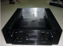
If you in China, I may deliver you a pair of ultra-large radiator fin.
48KG
Attachments
If you in China, I may deliver you a pair of ultra-large radiator fin.
48KG
Now that is pretty... (amazing what things a geek like me finds to be beautiful)
Thanks
At this stage I am not too worried about getting 50W exactly. I am guessing whichever heat sinks I find in the end will limit me. IT will be a process of switching it on at very low bias current and slowly turning up over a matter of a few hours while measuring the temp.
I was just curious about the effect that a 45V rails will have on the 2 pairs of devices on this design , compared to the 3 to 4 pairs used in other designs.
My power supply that i am going to test with is +-35V DC 40000uF per rail
(25V AC 500Va toroidal)anyway..
I'll decide from their if I can or even need to go higher.
Realistically most people could live happily with 10 Watts of class-A power.
Nahhh, it is absolutely beautiful, it's not a matter of personal taste. Every body SHOULD love it 😀Now that is pretty... (amazing what things a geek like me finds to be beautiful)
My good brothers have a cabinet factory.😀
A group buy for one of those beauties for the KSA-50 would be awsome 😉
Per rail. Per channel was 80.000uF😉
Thank you a lot Neychi for the input
4 x 20.000 uf 😱
Hip Hip Horeee ... Uncle Jacco Here

Last edited:
- Status
- Not open for further replies.
- Home
- Amplifiers
- Solid State
- KSA50 AMP(New production Live in...)