The Different is in the INPUT STAGE
- Jan Dupont use 2 x MPSA42 - 92, 2 x 2sa970 - 2sc2240 & 2sc3955
- Pink Mouse use 3 x MPSA 42 - 92
- Gxcnabin use 3 x 2sa970 - 2sc2240 & 2SD669
Some people build Jan and pinkmouse version and make comparable
of them, a view diy compare them with commercial version too
Hi! Pocoyo
prepares when anything assembles, I am waiting for your evaluation report.
abin
Your Modul will excellent Abin but my friend
Atok Purnomo will give you evaluation first
someone in KSA50 PCB change MPSA42-92
with bent the feets of 2sa970 & 2sc2240
not a lot of people notice of his research
(same as your board now)
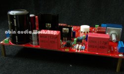
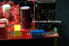
do you planning to add 2 more caps supply (6 supply caps @35mm)
in your new pcb, so we will get 60.000uf - 72.000uf per channel
( for heatsink people can use 35mm or 2 x 20mm )
The other consideration, should we add 1-2 pair mj21193-21194 ?
so we will use 3 - 4 pair mj21193-21194
if i use industrial caps 15.000uf, i will give bad medicine here
and if i looks for 22.000uf the price are so expensive
the best way used 6 pcs elna for audio 12.000uf 63v
this is economical, effective & efficient. Not a promotion 😱
Atok Purnomo will give you evaluation first
someone in KSA50 PCB change MPSA42-92
with bent the feets of 2sa970 & 2sc2240
not a lot of people notice of his research
(same as your board now)
do you planning to add 2 more caps supply (6 supply caps @35mm)
in your new pcb, so we will get 60.000uf - 72.000uf per channel
( for heatsink people can use 35mm or 2 x 20mm )
The other consideration, should we add 1-2 pair mj21193-21194 ?
so we will use 3 - 4 pair mj21193-21194
if i use industrial caps 15.000uf, i will give bad medicine here
and if i looks for 22.000uf the price are so expensive
the best way used 6 pcs elna for audio 12.000uf 63v
this is economical, effective & efficient. Not a promotion 😱
Thanks your suggestion, I am waiting for your friend's evaluation to report, the possible words please upload some material. I want to make most perfect KSA50, thanks!
Gxcnabin
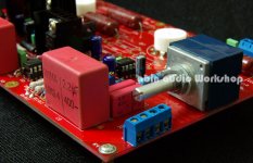
I like the underlying concept of your board- having minimal wiring and having the PSU so close to the output devices is a good idea. However I am concerned about:
1. The board is is too small for a hefty PSU.
2. The KSA can get quite hot. Having just 4 flatpack output devices is possibly not a good idea in terms of longlivity. I would rather err on the side of caution by having three pairs with wider spacing. If you living in the artic areas it possibly a safe option but if you living in a dry area and it get's to summer the class A amps run dangerously hot !
3 Having thicker tracks on the board for the PSU.
Regards
Jozua
Gxcnabin
I like the underlying concept of your board- having minimal wiring and having the PSU so close to the output devices is a good idea. However I am concerned about:
1. The board is is too small for a hefty PSU.
2. The KSA can get quite hot. Having just 4 flatpack output devices is possibly not a good idea in terms of longlivity. I would rather err on the side of caution by having three pairs with wider spacing. If you living in the artic areas it possibly a safe option but if you living in a dry area and it get's to summer the class A amps run dangerously hot !
3 Having thicker tracks on the board for the PSU.
Regards
Jozua
Thanks you to my board approval.
Also thanks the question which you raise.
Has carried on the strict computation before the design to the electric current, you worried should not exist.
Gxcnabin .....
2. The KSA can get quite hot. Having just 4 flatpack output devices is possibly not a good idea in terms of longlivity. I would rather err on the side of caution by having three pairs with wider spacing. If you living in the artic areas it possibly a safe option but if you living in a dry area and it get's to summer the class A amps run dangerously hot !
Hi Abin
I just prepared 4pair output (pinkmouse PCB) before i met your board
Before this i asked to you
- How big bias do you run for it ?
- Are you run bias for 50W ?
- How long you tested them ?
- For the thermal measurement, how big bias you use for them
Thank you
Best regards, jeffry
Hi Abin
I just prepared 4pair output (pinkmouse PCB) before i met your board
Before this i asked to you
- How big bias do you run for it ?
- Are you run bias for 50W ?
- How long you tested them ?
- For the thermal measurement, how big bias you use for them
Thank you
Best regards, jeffry
Hi! Pocoyo
What degree now assembled to?
(- How big bias do you run for it ?)
I test when the quiescent current uses 800mA,
Because did not have the official manufacture box body,The test uses the radiator fin is too small, can only use 800mA.
(- Are you run bias for 50W ? )
yes!
(- How long you tested them ?)
Uninterrupted circular telegram 24 hours later test data.
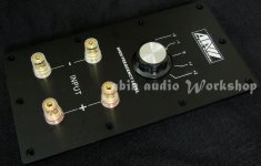
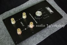
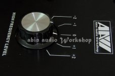
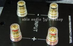
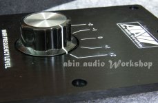
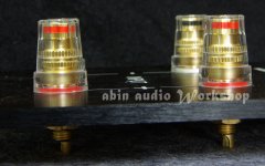
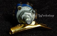
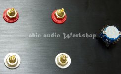
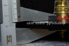
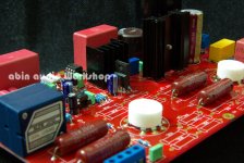
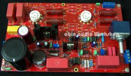
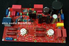
Today has free time, on DIY this, Entire aluminum alloy input board.
Attachments
-
 IMGP3133.JPG113.2 KB · Views: 380
 -
 IMGP3135.JPG130.7 KB · Views: 370
 -
 IMGP3136.JPG89.8 KB · Views: 367
 -
 IMGP3137.JPG97.3 KB · Views: 357
 -
 IMGP3138.JPG97.1 KB · Views: 338
 -
 IMGP3140.JPG99.6 KB · Views: 90
 -
 IMGP3143.JPG122.7 KB · Views: 123
 -
 IMGP3142.JPG105 KB · Views: 101
 -
 IMGP3141.JPG110.1 KB · Views: 93
a beauty case. ugly knob.
please find a good looking knob for your case.
😀
really nice plate, are you planning in making a subwoofer?
http://www.diyaudio.com/forums/multi-way/166551-12-inch-wooden-horn-speaker-4.html
You in the bali traveling?
The test uses PCB has not sent from the factory, but must wait again on for several days.
As soon as has the test result to remember that tells me it.
Thanks!
The test uses PCB has not sent from the factory, but must wait again on for several days.
As soon as has the test result to remember that tells me it.
Thanks!

Expecting to get all my parts end of this week early next week.
I'll post as soon as i have something to show in the next 2 weeks
I'll post as soon as i have something to show in the next 2 weeks
- Status
- Not open for further replies.
- Home
- Amplifiers
- Solid State
- KSA50 AMP(New production Live in...)