Thanks metal ... don't know how that happened!
Anyway. After playing around with the circuit some, there are some interesting aspects:
The differential stage:
The "missing" current source, seems to work well at first sight. Adding a constant current source, does not necessarily improve distortion performance, it is actually hard to beat the single R3 resistor!!!
But distortion is heavily dependent on the current through the input stage. Having only a resistor the current is dependent on the supply voltage. That is R3 needs to be “tuned” to the Vcc/Vss used! …. Not so smart.
This of course also makes for a bad PSRR …
Remedy: use of constant current source.
Take a look at the LifeForce 55 PCB
I’ll bet that Hugh is using a constant current source based on a pnp transistor and a green LED. This feeding a differential stage which is further balanced by a current mirror (makes up for the 5 small signal transistors on the PCB 🙄 )
Noise floor is impaired due to use of high value resistors in input and feedback network:
Something like R1 = 10k, R8 = 330, R9 = 10k …. Will work better
The bootstrapping of the VAS stage, also seems to perform quite well, but if you already have constant current source in the input, it only takes one transistor to make the same for the VAS stage (use of same reference) ….. and save a big C4 …. Guess that’s the big cap in the middle of the LifeForce 55 board …..
…. But doing that and you are back to a well known Douglas Self type of amp 😱
I have no doubht that the LifeForce 55 is a good and probably well sounding amp but stating “The Lifeforce uses extremely sophisticated circuit techniques” ….. is to my mind a bit over the top … when it is somewhat less sophisticated than a blameless!!!!
Why is R16 and R17 used??? To prevent oscillation?
(on the LifeForce 55 PCB also note that 4 diodes are used, two across R2 and 2 across C2, for safety reasons)
Baldin, forgive me but your logic is flawed - you take a number of guesses about the topology of the Lifeforce: "I’ll bet that Hugh is using a constant current ....." ; "Guess that’s the big cap in the.........." Then based on these guesses you are ready to make a bullish proclamation "when it is somewhat less sophisticated than a blameless!!!!" You need to re-think this, I believe or re-frame it into another guess?
I have recently bought Hugh's new amplifier a Naksa & I am stunned by it's performance & I've heard & have had a lot of amps in my & others systems & this is in the top drawer of amplifiers!
I have recently bought Hugh's new amplifier a Naksa & I am stunned by it's performance & I've heard & have had a lot of amps in my & others systems & this is in the top drawer of amplifiers!
Hi jkeny
Well I wasen't trying to bully anything or anyone (though I do think the proclamation on the Aspen homepage is a bit to much) .....
As I wrote I have no doubth that the amp is sounding really good, and what interested me in the first place was actually to study whether this might be because it has a predominant even order distortion pattern .... which I thought might be caused by, the bit old fashion use of bootstrapping and no curent source ... as I CAN see from the baby AKSA circuit in this thread ......
As I also said both of these solutions actually work quite well wrt. distortion. What I wantend to point out, and again this is towards the circuit presented here, is that I think a current source would be an improvement ..... and that I think then new'er AKSA amps actually has this "improvement" in place .... but yes I don't know for sure.
So please read my comment as a comment to the amp presented in this thread, and not to your new Naksa
(The thing about distortion, was something I came to think about when I compared a lot of distortion measurements of ScanSpeak units, to other speaker units. Some of the SS units have a remarkably low 3. order harmonic, while a not so low 2. harmonic as some of their competitors. Odd order harmonics makes the sound more clinical, cold or metalic. So my thinking was actually that the likeings by many of these AKSA amps might be caused by a similar thing .... but I might be quite wrong)
"So please read my comment as a comment to the amp presented in this thread, and not to your new Naksa" I thought you meant it as a comment on the Lifeforce but never mind!
Hi Baldin,
You are right. The LF55 is primitive because it uses high impedance fb resistors, and a bootstrap. Nowhere near as sophisticated as the Self amp.
Furthermore, it does not use a current mirror in the input stage. Quelle horeur!!
All these primitive choices are made for very good reasons. I have been down this path for twenty years. I have tried them all. My choices are based on one quality only: performance. You probably don't realise, but there are a couple of LF55s in Copenhagen. Perhaps you might like to hear one?
Nice blog, your photography is excellent and you are learning a lot.....
Hugh
Hi Hugh
year the current mirror was just a bold guess 🙂 ..... but I guess it's still right about the current source .... or not?
Get me right, I do not think more transistors necessarily equals better sound ..... that is actually why I find your amps quite interesting
Beat regards Baldin
year the current mirror was just a bold guess 🙂 ..... but I guess it's still right about the current source .... or not?
Get me right, I do not think more transistors necessarily equals better sound ..... that is actually why I find your amps quite interesting
Beat regards Baldin
Baldin,
Yes, the LF uses a CCS to supply the front end, based around an LED voltage reference.
If you were designing for a resistive load, a CCS on the VAS would be superior.
But, you are designing for an active load, a speaker, with back emf from both the inductances in the load and from the motor, comprising the voice coil and the magnet.
The amp takes fb from the speaker, not just the output, and this back emf is superimposed onto the fb signal applied to the front end. The bootstrap gives an interaction with this back emf, since the lower resistor now has a varying dynamic resistance due to the differential voltage across it caused by this back emf.
This modifies the distortion profile of the VAS, creating more even than odd order distortion, since the current through the VAS is not constant at all.
You need to build these circuits, and carefully listen to the slighly different sonic presentation. This is empirical work; relying solely on the theory or simulations will get you close, but not all the way.
In the final assessment, it is only the sound which represents the end of the line. Right or wrong, the market has reached this conclusion decades ago. Theory is necessary, but it is based on flawed models. You really do need a lab for this.
Cheers,
Hugh
All these primitive choices are made for very good reasons.
Presumably for sound quality reasons going on what I've learned so far. So how does the resistive LTP load sound as compared to current mirror loading?
Better
In what respects better?
<edit> I'll just add here a supplemental couple of questions - when you compared the two, did you take account of the doubling of the slew rate in going from resistive load to current mirror load? Or did you compare amps with the same slew rate?
Last edited:
I haven't the time. I'll say it again: better.
I have no expectation you will believe me and neither should you have any expectation I should explain it in highly arguable technical terms, accordingly, try it yourself.
I have no expectation you will believe me and neither should you have any expectation I should explain it in highly arguable technical terms, accordingly, try it yourself.

Neither of you have to call. Big brother is always watching. Watching and erasing the unnecessary posts.
Let's continue cordially please.
Thanks metal ... don't know how that happened!
Anyway. After playing around with the circuit some, there are some interesting aspects:
The differential stage:
The "missing" current source, seems to work well at first sight. Adding a constant current source, does not necessarily improve distortion performance, it is actually hard to beat the single R3 resistor!!!
But distortion is heavily dependent on the current through the input stage. Having only a resistor the current is dependent on the supply voltage. That is R3 needs to be “tuned” to the Vcc/Vss used! …. Not so smart.
This of course also makes for a bad PSRR …
Remedy: use of constant current source.
Take a look at the LifeForce 55 PCB
I’ll bet that Hugh is using a constant current source based on a pnp transistor and a green LED. This feeding a differential stage which is further balanced by a current mirror (makes up for the 5 small signal transistors on the PCB 🙄 )
Noise floor is impaired due to use of high value resistors in input and feedback network:
Something like R1 = 10k, R8 = 330, R9 = 10k …. Will work better
The bootstrapping of the VAS stage, also seems to perform quite well, but if you already have constant current source in the input, it only takes one transistor to make the same for the VAS stage (use of same reference) ….. and save a big C4 …. Guess that’s the big cap in the middle of the LifeForce 55 board …..
…. But doing that and you are back to a well known Douglas Self type of amp 😱
I have no doubht that the LifeForce 55 is a good and probably well sounding amp but stating “The Lifeforce uses extremely sophisticated circuit techniques” ….. is to my mind a bit over the top … when it is somewhat less sophisticated than a blameless!!!!
Why is R16 and R17 used??? To prevent oscillation?
(on the LifeForce 55 PCB also note that 4 diodes are used, two across R2 and 2 across C2, for safety reasons)
Hi Baldin,
The whole point of this thread is an amp based on the conceptual schematic of the AKSA 55. Hopefully on the way we can drag a few of Hugh's unpublished "gems" to add or enhance this schematic. The ultimate goal would be to have an AKSA 55 N+ but this would require a lot of give on Hugh's behalf and it isn't going to happen overnight, if ever.
All the stuff about CCS, current mirrors doesn't belong here, and by default PSRR is irrelevant. Let's keep close to the original schematic.
regards
Hi Baldin,
You should be investigating SiliconChip designed amps from the last 10 years. They are based on D. Self's blameless and have very little distortion (0.006% or was that 0.0006%). 😀 Some of Randy Slone's design also fit your bill.
regards
You should be investigating SiliconChip designed amps from the last 10 years. They are based on D. Self's blameless and have very little distortion (0.006% or was that 0.0006%). 😀 Some of Randy Slone's design also fit your bill.
regards
What a great thread (well, most of it). Thanks Greg and Hugh for the ongoing contribution here. Tons to learn...
[EDIT] Oh, I should add that when you speak of Slone's 'book', I can't help but wonder which one of the 3 Slone books I have that you might be referring to.
..Todd
[EDIT] Oh, I should add that when you speak of Slone's 'book', I can't help but wonder which one of the 3 Slone books I have that you might be referring to.
..Todd
Last edited:
Folks,
I'm very busy, have a lot on my plate, and I really cannot any longer indulge the forum. It's good fun, but too time consuming.
Anyone really interested is welcome to privately email me, but be aware I will only answer when I have the time. This is not to be rude or arrogant, simply the constraints of time and energy.
My email is on my website, I endeavour to answer all of them. Needless to say, I always respond well to courtesy.
Cheers,
Hugh
Baldin,
Yes, the LF uses a CCS to supply the front end, based around an LED voltage reference.
If you were designing for a resistive load, a CCS on the VAS would be superior.
But, you are designing for an active load, a speaker, with back emf from both the inductances in the load and from the motor, comprising the voice coil and the magnet.
The amp takes fb from the speaker, not just the output, and this back emf is superimposed onto the fb signal applied to the front end. The bootstrap gives an interaction with this back emf, since the lower resistor now has a varying dynamic resistance due to the differential voltage across it caused by this back emf.
This modifies the distortion profile of the VAS, creating more even than odd order distortion, since the current through the VAS is not constant at all.
You need to build these circuits, and carefully listen to the slighly different sonic presentation. This is empirical work; relying solely on the theory or simulations will get you close, but not all the way.
In the final assessment, it is only the sound which represents the end of the line. Right or wrong, the market has reached this conclusion decades ago. Theory is necessary, but it is based on flawed models. You really do need a lab for this.
Cheers,
Hugh
Thanks Hugh for a very informative answer.
I can't believe I just read all pages of this thread.
I was about to bring up my own bootstrap modification but the aim is to reproduce the AKSA in spirit and I'm sure Hugh has tested my idea before... Gets me thinking, if back EMF matters so much for the sonics, then perhaps output impedance has to be factored in with the aforementioned CLG, OLG stuff? AndrewT was "close"...
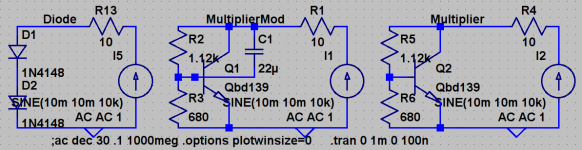
Also, in the last schematic posted, there is no capacitor bypass for the Vbe multiplier. Hmm.
I remember in the days of HAKSA, the question was brought up about which was better, passive diode bias or Vbe multiplier. I brought up simulations and showed that the Vbe multiplier behaves weird owing to the type of transistor most often used (low Hfe 20W types) (AKSA responded with interest, which leads me to believe he hadn't tried it before). The surprising thing is that the multiplier's impedance was actually WORSE than the diode string's. A 22uF cap B-C really helps with this. Now impedance is markedly improved (by 16db), justifying its use over the trivial diode string. Plots attached.
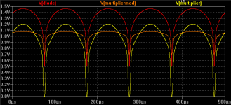
Trivial, oh so trivial, but what the hell. Well the numbers are interesting to ponder. Upwards of 1KHz it doesn't matter when a 22uF bypass is used, but again for the 100Hz-1KHz region impedance is 16db less (owing to the higher impedance and longer RC constant seen by the B-C cap). The bass end can be extended easily by increasing the B-C cap (20Hz for 100u), an improvement which otherwise would require a much larger bypass cap (2500uF!). The appeal to me is that instead of walking with frequency, the impedance drops to some point early on and stays there for all of the audio band; very nonreactive. It would be nice for someone to test this sonically (trying not to lodge foot in mouth).
- keantoken
I was about to bring up my own bootstrap modification but the aim is to reproduce the AKSA in spirit and I'm sure Hugh has tested my idea before... Gets me thinking, if back EMF matters so much for the sonics, then perhaps output impedance has to be factored in with the aforementioned CLG, OLG stuff? AndrewT was "close"...
Also, in the last schematic posted, there is no capacitor bypass for the Vbe multiplier. Hmm.
I remember in the days of HAKSA, the question was brought up about which was better, passive diode bias or Vbe multiplier. I brought up simulations and showed that the Vbe multiplier behaves weird owing to the type of transistor most often used (low Hfe 20W types) (AKSA responded with interest, which leads me to believe he hadn't tried it before). The surprising thing is that the multiplier's impedance was actually WORSE than the diode string's. A 22uF cap B-C really helps with this. Now impedance is markedly improved (by 16db), justifying its use over the trivial diode string. Plots attached.
Trivial, oh so trivial, but what the hell. Well the numbers are interesting to ponder. Upwards of 1KHz it doesn't matter when a 22uF bypass is used, but again for the 100Hz-1KHz region impedance is 16db less (owing to the higher impedance and longer RC constant seen by the B-C cap). The bass end can be extended easily by increasing the B-C cap (20Hz for 100u), an improvement which otherwise would require a much larger bypass cap (2500uF!). The appeal to me is that instead of walking with frequency, the impedance drops to some point early on and stays there for all of the audio band; very nonreactive. It would be nice for someone to test this sonically (trying not to lodge foot in mouth).
- keantoken
Attachments
hi keantoken,
Very interesting and simple to try. I now have 5 B-AKSAs built, 4 identical so I will note this one down as a experiment. The cap across B-C rather than the traditional C-E will be easier on this PCB.
regards
Very interesting and simple to try. I now have 5 B-AKSAs built, 4 identical so I will note this one down as a experiment. The cap across B-C rather than the traditional C-E will be easier on this PCB.
regards
Last edited:
- Home
- Amplifiers
- Solid State
- Based on Hugh Dean's AKSA 55