Combining glass, sand and iron (I'll be using an MC step up), and various ideas picked up here. The basic schematic is from Dmitry (don't know if he posts here, but has some good stuff on his site): www.dmitrynizh.com/3a5-phono.htm.
The HV supplies are based on Salas' shunt reg., and the transistors in the filament supply are those recommended by Rod Coleman. Gyrator from discussions among Wavebourn, Michael Koster, Kenpeter, Revintage, Smoking amp, etc..
I still have to build the case work, so I haven't given it a listen. As shown, the response is within 0.3dB from 20Hz to 20kHz. I can tweak the network resistor values a bit, to get it even closer Channel to channel it's within 0.1dB over the entire range, if I match the tubes. (BTW, the Hagerman calculator seems off to me. I actually measured the Rp of the tubes in the circuit (which were very close to the values measured from the curves), so my calculations there are accurate, and I was a little suprised that my initial measurements were off at the 20kHz end by 0.75dB. When I calculated the time constants from the Hagtec calculator values, they were lower than the expected 75 and 3180us.)
The circuit values are as tested.
Sheldon
Attachments
Last edited:

Thought occurs that I maybe should have started this tread in the analog source section. At any rate, I adjusted the RIAA resistor values. I now get within 0.2dB, from 12Hz to 100kHz. That takes away the 50kHz compensation, but I'm not so sure it's needed. I can't hear the difference with or without it, in my other phono amp (but, given my hearing, that can't be assumed to be the universal experience).
The series resistor for the first stage was increased to 46.5k and the shunt resistor was changed from 2k to 1k. The second stage series resistor was increased to 39k and the shunt resistor from 4.7k to 5k.
The series resistor for the first stage was increased to 46.5k and the shunt resistor was changed from 2k to 1k. The second stage series resistor was increased to 39k and the shunt resistor from 4.7k to 5k.
Attachments
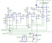
Final schematic, with actual common connections shown. Almost a star, except that it was a little easier to connect the RIAA compensation shunts and the 2nd and 3rd stage grid leak resistors to the filament buss. It's a 16gauge copper wire, and the final segment is short, so it shouldn't cause problems.
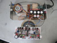
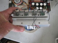
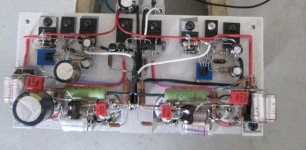
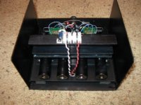
Lashed it up and plugged it into the system to check for subjective noise performance. Haven't scoped it as I tripped over my scope probe and broke it a few days ago. Noise is all white noise and similar in level to my other pre (modification of Steve Bench design). At any rate, well below record surface noise. The simple CCS for the filaments works well. I compared it with battery power and could detect no difference in noise level. Confirmed (no shock here) that mechanical isolation will be necessary to manage microphonics. For now, a thick strip of felt for it to sit on tames it.
Haven't yet listened to music. Will do that when I get the case for the preamp section done, and can mount the step up trannies. Will also try a head amp, but need a few parts.
I haven't prompted any response, so must not be anything controversial here.
Sheldon
Attachments
Last edited:
OK, I'll be controversial. Why only 35V on the first stage plate? What's the second harmonic distortion look like?
OK, I'll be controversial. Why only 35V on the first stage plate? What's the second harmonic distortion look like?
Nice to see you here, thanks for the comments.
I just followed Dmitri's recipe for operating points.
The voltage on the first stage is a consequence of the filament biasing used. Haven't measured the harmonic distortion (fried the input on my external sound card a while ago - might be a trend starting on broken test gear), but looking at the plate curves suggests that I'm on up on a reasonably linear part of the 0V grid curve, and I'm not swinging much. It's a little odd interpreting this, as one side of the filament is at 1.3V (slightly starved) and common side at 0V. But I assume the grid curves are derived as referenced to common.
I can certainly play with it, as it's a simple matter to adjust the B+ with a trim pot. That will change the third stage plate voltage as well, as the gyrator reference is the first stage B+. But, higher plate voltage there should be no problem. Or, I can put a pot before the bias connection and trim it down.
Sheldon
Everything seems to be checking out fine, with one exception - so far. I get a significant turn on bump. I checked DC at the output and it seems to spike almost to the full B+, swing down, then rise gradually as the bias cap charges.
The B+ itself, rises quickly - within a second or so - but without overshoot.
Looking at the schematic, I'm stumped. The only thing I can think of is the safety diode from the gate of the SK170 to the B+ for the gyrator. Does it have enough capacitance to send the gate of the 170 momentarily to B+? Or does it have something to do with the gate capacitance of the 10m45?
Sheldon
Interesting application of DHTs. I have a bunch of 3A5s since I had a plan to use them in guitar effects pedals. Turns out they are too microphonic in that application. Rubber mounting the tubes and having silicone rings around the tubes helpes of course, but when a guitar is at full that still wasn't enough.
I look forward to your final conclusion regarding a phono pre with these tubes. I wouldn't mind putting mine to good use.
If the tubes are cold on turn-on the CCS would surely drive the output to b+. My guess.
I look forward to your final conclusion regarding a phono pre with these tubes. I wouldn't mind putting mine to good use.
If the tubes are cold on turn-on the CCS would surely drive the output to b+. My guess.
If the tubes are cold on turn-on the CCS would surely drive the output to b+. My guess.
Thanks. I tried a few different things. Even with the filaments on before B+ is applied, there is a significant turn on rise, and even steeper turn off bump. The slow turn on of the bias with the RC section doesn't help, so I eliminated it.
I think it would be pretty easy to use a mosfet and an RC delay to the gate, to bring the power up slowly. Or I could simply have a mute relay with some delay. But the turn off bump is actually harder to deal with, since it occurs within a second of the main being switched off. Clever ideas anyone?
Sheldon
Or I could simply have a mute relay with some delay. But the turn off bump is actually harder to deal with, since it occurs within a second of the main being switched off. Clever ideas anyone?
Use turn-on and turn-off sequencing of the mute relay. That's pretty simple and cheap to do.
Use turn-on and turn-off sequencing of the mute relay. That's pretty simple and cheap to do.
True, it would be fairly simple, had I left provision to run some extra wiring from the raw supply to the output section. Right now, I just have HV, Filament, both commons, and earth. So I have to ponder this a bit.
With a latching relay, and the starting position with the outputs shorted to common, I just need to make some kind of single pulse circuit that is delayed a few seconds. I've not done pulse stuff before, but should be something fairly easy to find. On the shut down side, I need a pulse in the opposite direction (or to the other coil with a dual coil relay). I assume can power the coil with a cap. But I need to detect a drop in the HV, and trigger the relay before the filament cools or the regulated HV falls out. HV does start to fall sooner than the regulated voltage, or the filament voltage. Ideas welcome.
If I can't cook up something, I'll just have a manual mute switch, and use a back to back zener to limit the output swing, so it won't break any SS gear it may be connected to. (nice thing about tubes is their ability to withstand momentary abuse).
Sheldon
Continuing thought, with the caveat that I know nothing about logic type circuits:
Starting condition is with outputs muted and amp off.
I need two circuits, one for power on, one for off. If I can generate two pulses, I can do the rest. Both need to be of sufficient length to trigger a latching relay (5mSec or so).
For power on, this pulse occurs a couple of seconds after power on. I guess the easiest is to generate the pulse when the voltage of the delay circuit reaches a determined level. This pulse opens the relay and un-mutes the outputs. This circuit should reset when the voltage falls below that level (power is off).
For power off, I need a circuit that supplies a pulse when the voltage falls below a predetermined level. I would power this from the raw HV input, as it falls before the regulated HV, or the regulated filament supply. This should reset when the control voltage goes above the trigger level.
So how to build these pieces?
Sheldon
Why use a latching relay? - just use a conventional low signal level reed relay with NC contacts. Delay the application of coil power with a simple transistor buffered RC circuit, and make sure that the moment the power is turned off the power supply to the coil is removed. (Also provide a diode controlled discharge path to that supply for the turn on delay RC.) Make the time delay long enough so that not much current is flowing when the contacts finally open - and 100 ohms or so of series resistance after the coupling capacitor and before the shunt relay contacts to prevent contact welding. (Reverse biased diode across relay coil windings if relay does not come with this feature by default. 5V/12V coils types are common even on eBay. Note I have used thousands of reed relays in ATE applications and they have no problem with coil continously powered in operation. Latching relays are less reliable IMHO and somewhat trickier to use.)
While you could use back to back zeners I would recommend probably not doing this because of the capacitance and linearity issues (admittedly slight as this is common audio practice with SS) - why mess up your clean signal path with a (theoretically) non-linear element? I would employ a diode clamp using symmetrical reverse biased low leakage/low junction capacitance diodes using some small 3V coin cells for the bias. (They would probably never need to be replaced if you choose silver oxide types.)
While you could use back to back zeners I would recommend probably not doing this because of the capacitance and linearity issues (admittedly slight as this is common audio practice with SS) - why mess up your clean signal path with a (theoretically) non-linear element? I would employ a diode clamp using symmetrical reverse biased low leakage/low junction capacitance diodes using some small 3V coin cells for the bias. (They would probably never need to be replaced if you choose silver oxide types.)
Last edited:
Why use a latching relay? - just use a conventional low signal level reed relay with NC contacts. Delay the application of coil power with a simple transistor buffered RC circuit, and make sure that the moment the power is turned off the power supply to the coil is removed.
Thanks Kevin. I've done the delay part for a number of projects. That is no problem. And the second part is not a problem - if I power the relay from a low storage source - a separate feed from the filament transformer. I've got a 5 pin connector from raw supply to the preamp. If I switch to a 7 pin connector, I can do it. Looks like I should just order a new connector.
Sheldon
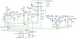
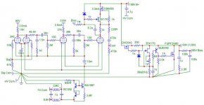
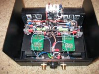
Finally had a chance to finish this up. Sounds very nice on initial listening. Nothing missing, very clean. It's nice and quiet - well below the surface noise. Maybe a touch more at full volume than my Steve Bench phono amp, but the gain is higher (about 45dB vs. 39dB), so signal to noise is just as good or maybe a little better. At the moment, I'm using it through a pair of Luhndahl 9206, 1:20 step up. Final schematic below:
A few words on the schematic. I followed Dmitry's values, with a few minor changes. The only real difference in the amp is cascode on the plate of the output tube. The output is taken from the mu follower. Looks like a lotta sand, but all the voltage gain is from the tubes. The rest of the sand is employed for making clean supplies of power.
All the components shown in this schema are in the amp chassis. The raw power supply is separate. There are two shunt supplies, one at 80V, one at 120V (thanks Salas for the design). The supplies are shared between channels.
Each channel has it's own filament CCS, but the cap multiplier is shared between the channels. The filaments are run slightly starved at about 2.2V, instead of 2.4V.
Attachments
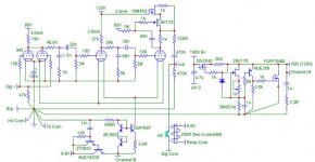
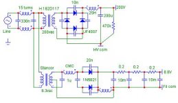
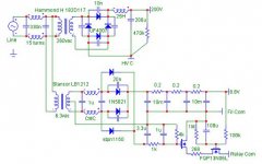
And the raw supply. Nothing exotic in the basic scheme. I did concoct a little supply for the muting relays (or relais). The relays are normally closed, so the outputs are muted at start up. And they must close on shut off, before the output from the amp drops.
In order for the relay to activate, both FET's in series must conduct. The FET with the large cap on the gate, turns on after a few seconds. On turn off, the relaly closes within a fraction of a second, as the RC time constants are much shorter for the other FET. Note that the dedicated diodes are necessary. The power to this FET gate has to be taken before the filament supply reservior, so that the power drops quickly after the mains switch is turned off. Probably better ways to do this, but it works perfectly.
In order for the relay to activate, both FET's in series must conduct. The FET with the large cap on the gate, turns on after a few seconds. On turn off, the relaly closes within a fraction of a second, as the RC time constants are much shorter for the other FET. Note that the dedicated diodes are necessary. The power to this FET gate has to be taken before the filament supply reservior, so that the power drops quickly after the mains switch is turned off. Probably better ways to do this, but it works perfectly.
Attachments
Last edited:
- Home
- Amplifiers
- Tubes / Valves
- Unholy Alliance Phono Amp