
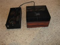
Final note on the chassis. The 3A5, being a DHT with a very thin filament, is microphonic. So it requires some isolation from vibration. The anodized aluminum frame that holds the tubes and regulators is like an inverted T bar. It sits on two reticulated foam rails, about 2x2x10cm. You can see these (grey) in post 19 and 20 if you look closely. Other methods, such as suspending the tube chassis, would work fine too, as will other dampening materials. I have felt feet on the body of the outer chassis. This combination seems to eliminate microphonic noise, unless I tap directly on the chassis. Even then, the ringing is quickly damped.
Sheldon
Sheldon
How much standing current the depletion CCS runs in the reg for Rs=200R?
Actually, I forgot to change that. It's 100R now, and about 30mA standing current.
Sheldon
Also noticed another change. I no longer have any caps in the cathode circuit. Found I didn't need them with the filament reg.
Last edited:
Does it leave about 20mA to the reg after it feeds what it feeds? Must be arranged to leave at least so to work good.
Each channel takes about 5mA, total 10mA for both. So about 20mA shunted.
Sheldon
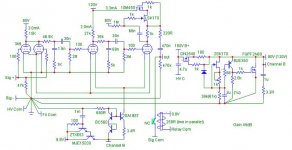
Updated Schematic:
Sheldon
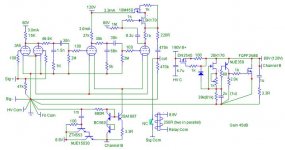
Updated Schematic:
Attachments
Last edited:
Another change to the schematic, one minor, one significant. I don't think I've missed any others, so this is current.
The significant change is the value of the bootstrap cap for the gyrator load on the output plate. I started with 8.2uf organic electrolytic. Then, looking at the resistor values, decided to try a much lower value film cap. That gave a much higher low frequency corner. Should have realized that, but I hadn't taken into account that the plate conduction is loading the circuit. The cap needs to be sized to account for the plate resistance (about 8k), and keep the plate at the same voltage as the FET gate. So, back to 8.2u, as there are already three low frequency corners (two internal coupling caps, and the output cap). I wanted to keep this corner low.
Minor change was to the current set resistor for the filament CCS. I decided to up the current so that the filaments are only slightly lower than spec. It's now at about 2.6V, vs. the 2.8V design center.
Sheldon
Attachments
Another change to the schematic, one minor, one significant. I don't think I've missed any others
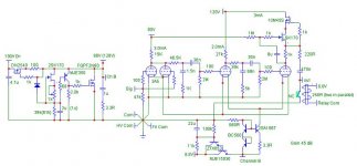
Wrong. Missed a big one. The cap multiplier in front of the filament CCS wouldn't be very useful as shown. It's actually as shown in this corrected version.
Attachments
Sheldon,
This is brilliant. How microphonic ended up being?
Will do some more research before coming back on this.
Cheers,
Ale
This is brilliant. How microphonic ended up being?
Will do some more research before coming back on this.
Cheers,
Ale
Sheldon,
This is brilliant. How microphonic ended up being?
Will do some more research before coming back on this.
Cheers,
Ale
Thanks, but I can't take too much credit. I just put together some good ideas from others on the forum. They created the building blocks.
The microphonics are not a big issue, or I should say that they are pretty easy to manage. You do have to have a separate sub chassis for the tube section. And it should be isolated from vibration. My sub chassis just sits on some foam pieces, with no hard connection to its outer chassis - only the wires - and that works fine. You can hear it if you tap on the chassis or the stand that it's on, but it doesn't ring. If the tubes have a rigid connection to the outside world, it can go into feedback mode if the music is loud enough.
My guess is that larger tubes, because they have a larger filament, could be a little more sensitive to vibration. Fact is, I think this gives DHT's some of their charm.
If I turn it up and listen closely, I can hear little clinking noises at the speaker while the tubes warm up. Kinda interesting, actually. Sounds like you are hearing right into the tube. The clinks are not obtrusive (have to be right up to hear them), and become more infrequent as the amp warms up. After a half hour or so, they are gone.
You will want to select tubes, especially for the input tube, as some are a little noisier than others. But they are cheap, and I've found a pretty good percentage of good matches and low noise tubes.
Sheldon
I have experienced the same clinking noise when warming up a pair of 45s. You have to place yourself ver close to the speakers. I thought the valve was defective and remove it. Will do the test again and see if it disappears after 30 min or so.
On a separate note, perhaps a dumb question: why all first stages in phono preamps have a resistor anode load. Will CCS be to noisy?
Thanks
Ale
On a separate note, perhaps a dumb question: why all first stages in phono preamps have a resistor anode load. Will CCS be to noisy?
Thanks
Ale
I have experienced the same clinking noise when warming up a pair of 45s. You have to place yourself ver close to the speakers. I thought the valve was defective and remove it. Will do the test again and see if it disappears after 30 min or so.
I think that those are just a function of the tube warming up and parts expanding. Not so different from noises you hear in a auto engine compartment when you turn it off after a drive.
On a separate note, perhaps a dumb question: why all first stages in phono preamps have a resistor anode load. Will CCS be to noisy?
I've not done the noise calculations, but see no reason you can't use one (maybe others will know). Just use a low noise transistor. The cascode gyrator in this amp could easily be converted to a current source.
Sheldon
Hi Sheldon,
3A5 works best around or just below 90V/5mA. But then you have to bias it higher so some kind of cathode resistor/diode arrangment is needed. Running the filament current(CCS) through the bias resistor makes it very small. Don´t know about noise in this low-level amp though. Hav eused it with success at line level.
3A5 works best around or just below 90V/5mA. But then you have to bias it higher so some kind of cathode resistor/diode arrangment is needed. Running the filament current(CCS) through the bias resistor makes it very small. Don´t know about noise in this low-level amp though. Hav eused it with success at line level.
Hi Sheldon,
3A5 works best around or just below 90V/5mA. But then you have to bias it higher so some kind of cathode resistor/diode arrangment is needed. Running the filament current(CCS) through the bias resistor makes it very small. Don't know about noise in this low-level amp though. Hav eused it with success at line level.
In the amp here - http://www.diyaudio.com/forums/atta...99104-unholy-alliance-phono-amp-3a5-phono.jpg - I'm running it at 35V and 1.5mA (both sections paralleled) for the input. Judging by the plate curves on Dmitry's site, that's still in a nicely linear area for small signals. The filament bias is resistance of about 6 Ohm (about 7 Ohm total, with a small resistor in series).
Noise performance is good - well below record surface noise, which is always the limiting factor in vinyl playback, even for the very best records.
Sheldon
Good morning,In the amp here - http://www.diyaudio.com/forums/atta...99104-unholy-alliance-phono-amp-3a5-phono.jpg - I'm running it at 35V and 1.5mA (both sections paralleled) for the input. Judging by the plate curves on Dmitry's site, that's still in a nicely linear area for small signals. The filament bias is resistance of about 6 Ohm (about 7 Ohm total, with a small resistor in series).
Noise performance is good - well below record surface noise, which is always the limiting factor in vinyl playback, even for the very best records.
Sheldon
I don't understand, Shaldon, how did you configure the filament bias for the first stage? the positive of the rod coleman goes to pin 4 and the pins 1 and 7 are put in parallel and to these is connected a 6 ohm R?
I ask why the 6 ohm R is not visible in the diagram.
In this case, could each single triode be considered as if it were connected to a 3 ohm R? (I hope I didn't say a big nonsense)!
I wonder why if I understand correctly this stage works very close to 0Vg but I wanted to understand how close. Looking at the curves published by Dimitry and Ale moglia on 3a5 to make the tube work at 35V and each section at 1.5mA, the grid voltage should be between about 0.6 and 0.8. Could you confirm?
Thank you.
I don't understand, Shaldon, how did you configure the filament bias for the first stage? the positive of the rod coleman goes to pin 4 and the pins 1 and 7 are put in parallel and to these is connected a 6 ohm R?
Yes, Pin 4 is connected to the following stage filament output.
I ask why the 6 ohm R is not visible in the diagram.
There is no 6 Ohm R. ?
In this case, could each single triode be considered as if it were connected to a 3 ohm R? (I hope I didn't say a big nonsense)! ?
I wonder why if I understand correctly this stage works very close to 0Vg but I wanted to understand how close.
The voltage across the filaments in parallel is 1.4V.
Looking at the curves published by Dimitry and Ale moglia on 3a5 to make the tube work at 35V and each section at 1.5mA, the grid voltage should be between about 0.6 and 0.8. Could you confirm?
I think so.
- Home
- Amplifiers
- Tubes / Valves
- Unholy Alliance Phono Amp