Hi, folks,
Recently I've got 70W PP output transformer, designed by myself, and decided to put it in bench test. I have not finished prototype amp yet, so its impossible to test trafo in real circuit.
Factory I ordered this device from did not have core of the size I wanted, instead, one was too small, and another was too big (probably enough for 150W unit). So 2nd.option was the obvious choice. The resulting product is a 8 kg monster.
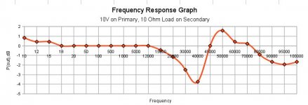
I used a generator 10Hz - 100 KHz with 10V 5 Ohm output (yes, 5 Ohm not 50). I connected it to primary (shunted with 5K resistor), and loaded secondary with 10 Ohm resistor (not wire-wound).
Transformer has quite unusual -4dB drop at 40 KHz and 1.5 dB peak at 50 KHz, the rest is fine up to 100 KHz. I do not have equipment to test above 100 KHz, or below 10 Hz, and do not I think this is necessary.
Voltage on primary was always constant, so this is not issue of generator output impedance. Frequency response from 10Hz to 20 KHz is linear +/-1 dB.
Do you have any idea what is the reason for so unusual behavior (or may be there is nothing at all to bother ?)?
If anyone have any other ideas of bench-testing (e.g. with square wave), I will be very welcome
Recently I've got 70W PP output transformer, designed by myself, and decided to put it in bench test. I have not finished prototype amp yet, so its impossible to test trafo in real circuit.
Factory I ordered this device from did not have core of the size I wanted, instead, one was too small, and another was too big (probably enough for 150W unit). So 2nd.option was the obvious choice. The resulting product is a 8 kg monster.
I used a generator 10Hz - 100 KHz with 10V 5 Ohm output (yes, 5 Ohm not 50). I connected it to primary (shunted with 5K resistor), and loaded secondary with 10 Ohm resistor (not wire-wound).
Transformer has quite unusual -4dB drop at 40 KHz and 1.5 dB peak at 50 KHz, the rest is fine up to 100 KHz. I do not have equipment to test above 100 KHz, or below 10 Hz, and do not I think this is necessary.
Voltage on primary was always constant, so this is not issue of generator output impedance. Frequency response from 10Hz to 20 KHz is linear +/-1 dB.
Do you have any idea what is the reason for so unusual behavior (or may be there is nothing at all to bother ?)?
If anyone have any other ideas of bench-testing (e.g. with square wave), I will be very welcome
Attachments
Last edited:
First of all your testing method is not the right one for a PP trans. You need a differential source for the primary. Then resistors IN SERIES at each side with the same value as the Rp of the tubes you want to use.
Secondary loaded with the nominal speaker value, grounded (ground the lead which gives the better FR.
Right now you are testing a SE transformer with Rsource of 5 Ohm !! (no tube with such low Rp as far as i know), and loaded with 5 Kohm // with the reflected load from the secondary.
Secondary loaded with the nominal speaker value, grounded (ground the lead which gives the better FR.
Right now you are testing a SE transformer with Rsource of 5 Ohm !! (no tube with such low Rp as far as i know), and loaded with 5 Kohm // with the reflected load from the secondary.
First of all your testing method is not the right one for a PP trans. You need a differential source for the primary. Then resistors IN SERIES at each side with the same value as the Rp of the tubes you want to use.
Secondary loaded with the nominal speaker value, grounded (ground the lead which gives the better FR.
Right now you are testing a SE transformer with Rsource of 5 Ohm !! (no tube with such low Rp as far as i know), and loaded with 5 Kohm // with the reflected load from the secondary.
Hi, schiller ! Thanks for suggestions! I have not connected tested transformer backward (secondary to the generator) as it have been done by many, I've connected primary (shunted with 5K resistor) straight to generator with 5 Ohm output impedance. So generator should "see" 5k shunt in parallel with 5k transformer input impedance. Please correct me if I'm wrong.
PS. One fellow noted a roll-off from 12 to 20 KHz. However, the whole chart is ONLY 6dB range, and this roll-off is just -1dB, its within norm.
Last edited:
A differential test would be good, but you should be able to get a reasonable idea just by using the right resistive loading. If testing single-ended this is 2xRp in series with the primary. Why are you worried about what impedance your sig gen sees? As long as this is high enough not to damage it the real issue is what impedances the transformer sees. The frequency response is secondary voltage/ sig gen output (not primary voltage).
What you are seeing is the HF resonance of the transformer.
What you are seeing is the HF resonance of the transformer.
I've connected primary (shunted with 5K resistor) straight to generator with 5 Ohm output impedance.
As mentioned the 5K resistor should be connected in series with the transformer, not in parallel to it. The generator should behave with any load even an open. You want the transformer to see an impedance representative of what the output tubes look like. It is rather hard to determine what the tubes look like since that depends on the class of operation, how they are connected, and how the feedback is implemented.
It is rather safe to say that 5 ohms does not represent any common tube. If you get the same peaking only more pronounced when the resistor is connected in series, you are looking at the usual resonance between the leakage inductance and the distributed winding capacitance. Since this is out of the audio band, build your amp and tweak the feedback as needed for proper square wave response.
As long as you don't have DC running through it, you absolutely can test it single-ended. Use a resistor of 2x the plate resistance of the tubes you're going to be using in series with the generator (no need for a primary shunt) and a load resistor on the secondary equal to the nominal load resistance (8R, if that's what the transformer is spec'ed for).
You will almost surely see an HF resonance- going to a larger core just about insures that your leakage inductance will be higher, so you're likely to have some limits on the high frequency response.
You will almost surely see an HF resonance- going to a larger core just about insures that your leakage inductance will be higher, so you're likely to have some limits on the high frequency response.
As mentioned the 5K resistor should be connected in series with the transformer,
I believe the first step in this excersize is to determine the true input Z of the transformer at some recognized test freq. like 1kz. Then that resistance is put in series to the primary for the following bandwidth test.
As mentioned the 5K resistor should be connected in series with the transformer, not in parallel to it.
As long as you don't have DC running through it, you absolutely can test it single-ended. Use a resistor of 2x the plate resistance of the tubes you're going to be using in series with the generator (no need for a primary shunt) and a load resistor on the secondary equal to the nominal load resistance (8R, if that's what the transformer is spec'ed for).
Many thanks, tubelab and SY! What is the purpose of resistor (equal to Raa or 2xRaa) connected in series with primary? In my setup generator will "see" 5K of primary anyway, and output impedance of this generator is only 5 Ohm. And what this resistor should be - equal to Raa or 2xRaa? Different people suggest different things, so I have to ask again.
PS. Yes, transformer is indeed too large, and those peaks and dips at 40-50 Khz may be result of this. On another side, even at max power flux is below 8000G, so distortions caused by the core are minimal. Additionally, this over-sized monster can handle 10mA DC imbalance of output tubes idle current without degradation of LF response. At least, it looks so on my calc sheet.
You are not very interested in what impedance the generator will see are you? To get a somewhat representative frequecy plot you will need to assure that your transformer "sees" a resonably representative driving impedance i.e. the output impedance of your PP stage.
In Class A the output impdance of a PP stage is approx 2xRp. To simulate this you need to put a resistor of 2xRp in SERIES with your generator.
/Olof
In Class A the output impdance of a PP stage is approx 2xRp. To simulate this you need to put a resistor of 2xRp in SERIES with your generator.
/Olof
Don't think about what impedance your generator will see. This is irrelevant. The issue is what impedance the transformer sees. At present it sees the 5 ohm output impedance of the generator, which is far too low. The 5k you added in parallel has no effect whatsoever - 5 in parallel with 5k is 4.995 !
You can add either two separate Rp resistors for balance, or one 2xRp resistor for simplicity. We are all telling you the same thing! The purpose of this resistor is to model the source impedance of the valve anode. Note that this is the anode impedance from the data sheet, not the matching impedance. I suspect that 5k may be the matching impedance, as it sounds too high for a triode and too low for a pentode?
You can add either two separate Rp resistors for balance, or one 2xRp resistor for simplicity. We are all telling you the same thing! The purpose of this resistor is to model the source impedance of the valve anode. Note that this is the anode impedance from the data sheet, not the matching impedance. I suspect that 5k may be the matching impedance, as it sounds too high for a triode and too low for a pentode?
As long as you don't have DC running through it, you absolutely can test it single-ended. Use a resistor of 2x the plate resistance of the tubes you're going to be using in series with the generator (no need for a primary shunt) and a load resistor on the secondary equal to the nominal load resistance (8R, if that's what the transformer is spec'ed for).
But chances are your test will not give you accurate results unless your signal generator is floating and you reference the CT to ground. Switching the Ground reference from SE (one end) to PP (the CT) changes all of the capacitive relationships and how they interact with the leakage. In some cases the differences are slight and in others they are drastic.
As stated earlier, Balanced drive with a pair of series resisters = Rp is the proper way to test this if your source is a triode. If it is a pentode or UL, the best bet is to use the tubes as your source.
dave
But chances are your test will not give you accurate results unless your signal generator is floating and you reference the CT to ground.
Why? The transformer doesn't "know" where ground is as long as you don't have both sides (primary and secondary) referenced to the same ground. That said, it's pretty easy to float the signal generator output, and that can simplify things.
Point taken about a resistor in each primary leg.
Actually, on second thought, if you split the series resistors as you say, nothing needs to be floated- the imbalance in impedance to ground from one half the primary to the other is only 5R.
Why? The transformer doesn't "know" where ground is as long as you don't have both sides (primary and secondary) referenced to the same ground. .
Physics dictate what a transformer "knows" and if you move the ground reference on a device I'd expect things to move.
dave
Most of the capacitance is within the windings and between the winding sections, so it should not be affected by the ground point. However, there will be some capacitance from windings to the core etc. and the effect of this will depend on ground point. What I would expect to see is that the HF resonance would show a similar structure either way, but the precise frequency would vary with gound point.
You might be able to simulate balanced drive by connecting the frame to the centre tap, but this won't be perfect as the frame itself has a capacitance which is normally grounded.
You might be able to simulate balanced drive by connecting the frame to the centre tap, but this won't be perfect as the frame itself has a capacitance which is normally grounded.
Last edited:
Yes ! Ground matters !
If you have access to some floating instruments, ground only the primary CT and tie it with one end of the secondary.
This being what happens in real life and even some SE OPT may exhibit different behaviour according to which end of the primary is grounded (in fact, tied to the secondary) specially above few tens of kilohertz where the resonances lie !
Without a floating generator and o'scope, consider feeding the OPT from the secondary and measure half primaries separately.
At this time, the difficulty is to have a generator with very lo internal impedance.
Yves.
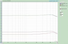
I hate it when I disagree with guys like Dave and Yves who know FAR more about the practicalities of transformers than I do. So, in my usual dumb fashion, I did the experiment. I had on hand a large core PP output transformer, 1k25 CT : 16R. Loaded the secondary with 16R. Drove the primary through a 3k resistor on each leg. Source was the output of an M-Audio 192 card. Secondary had the common lead (black wire) grounded, measurement picked off the 16R lead.
The top two curves (nearly coincident) show balanced drive to the primary. It didn't seem to matter significantly if the primary CT was grounded or not. Going to a single ended drive by shorting one phase to ground gave the curve on the bottom. The level drops 6dB as expected, but the Q of the HF resonance is higher as is the f3. These are not huge changes (a few tenths of a dB), but they're very easily measurable.
To see if the level was the cause (rather than the measurement topology), the balanced drive measurement was repeated at a 5dB lower level. That's the middle curve- it can be seen to replicate the higher level curve, thus one may conclude that the cause of the difference was indeed the measurement method.
So... follow their advice, not mine.
Attachments
What is ground?
It's not ground per se but connecting taps to the same AC reference that changes the response. Capacitance to the core doesn't actually seem to be much of a factor usually.
I think you can have one point in your measurement rig at ground if everything else is floating. It's when you change the relative AC reference between taps, i.e. AC voltage does or does not appear between a given pair of winding taps or ends, that the capacitive load between the windings changes.
The test setup needs to carefully duplicate the relative AC signals and the correct impedances on all the windings or the result will not be representative of the in circuit performance.
Interesting how many people seem to be speculating about this when actual measurements are so informative!!
PS SY crossed posts; Thanks for doing the test! sometimes the effect is way more dramatic!
PPS There are circuits one can think up using floating windings that have no tap at any reference potential. In-circuit measurement is probably the best bet here. It's all about how much AC signal voltage occurs between windings in a section or in proximity to each other.
Last edited:
SY, feeding the primary with two equal resistors from an unbalanced sig gen is an acceptable "pis aller" !
Specially using two 3K res into a 1K25 reflected load 😎
A plot of the voltage remaining at (each) primary with shorted secondary will give a good vision of the leakage inductance.
As we all know, we should measure nothing (0 volts) at any frequency if the OPT were "ideal" -i.e. reflecting a true shorted circuit 🙂
SY, feeding the primary with two equal resistors from an unbalanced sig gen is an acceptable "pis aller" !
That's what my graphs compare, balanced drive through two 3k resistors and an unbalanced drive, but the same 3k resistors in each transformer leg. Close, but noticeable different.
- Status
- Not open for further replies.
- Home
- Amplifiers
- Tubes / Valves
- PP Output Transformer Testing Puzzle