hey sy,
aside from the issues with the OP's test setup, I believe he drove the transformer end to end rather than the way you drove it (1/2 end to ground) leaving the other half out of the mix . I have seen and measured plots quite similar to his and it has always been a ground reference situation.
Unfortunately, the details hold the answers and if we don't document things properly, we may do more harm than good.
dave
hey sy,
aside from the issues with the OP's test setup, I believe he drove the transformer end to end rather than the way you drove it (1/2 end to ground) leaving the other half out of the mix .
dave
Yes, I connected transformer primary end to end to the generator. In class A for example both tubes are conducting all the time, so what exactly is wrong with this kind of connection?
hey sy,
aside from the issues with the OP's test setup, I believe he drove the transformer end to end rather than the way you drove it (1/2 end to ground) leaving the other half out of the mix . I have seen and measured plots quite similar to his and it has always been a ground reference situation.
Unfortunately, the details hold the answers and if we don't document things properly, we may do more harm than good.
dave
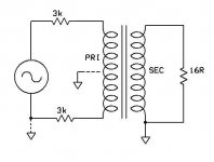
Just to be clear, this is the setup I used for the measurements shown before.
Attachments
Yes, I connected transformer primary end to end to the generator. In class A for example both tubes are conducting all the time, so what exactly is wrong with this kind of connection?
For a PP transformer the CT is at ground potential and moving that to another part of the coil can have interesting effects. Since you have the transformer try it and see what happens.
Also are you connecting the CT to the ground side of the secondary? If so, there is a reasonable chance that leaving the entire thing floating will eliminate the dip.
dave
Hey Sy,
Did you the CT ground connected for your "SE Drive"?
dave
No, only for the balanced drive.
Sy,
Can you repeat the test with the actual coil referenced to ground and not isolated by the 3K resistor?
dave
Can you repeat the test with the actual coil referenced to ground and not isolated by the 3K resistor?
dave
Sure, though it might not be until Saturday (getting into my lab during the week is a challenge!).
In class A for example both tubes are conducting all the time, so what exactly is wrong with this kind of connection?
Nothing, I belive you have it right. Since the Class A PP both tubes are conducting 360 deg. your sig. gen has to be across both coils with the series resistance that equals your primary Z. And since the CT is B+ and not ground you should float it. However, you still have not determined your tranny's primary Z. How can you simulate the tube to go with your tranny if you don't know the input impedance first? You must calculate that with a different test.
Nothing, I belive you have it right. Since the Class A PP both tubes are conducting 360 deg. your sig. gen has to be across both coils with the series resistance that equals your primary Z. And since the CT is B+ and not ground you should float it. However, you still have not determined your tranny's primary Z. How can you simulate the tube to go with your tranny if you don't know the input impedance first? You must calculate that with a different test.
Primary Z is 5K.
Primary Z is 5K.
That wasn't clear from your opening post.
Recently I've got 70W PP output transformer, designed by myself, and decided to put it in bench test. I have not finished prototype amp yet, so its impossible to test trafo in real circuit.
Factory I ordered this device from did not have core of the size I wanted, instead, one was too small, and another was too big (probably enough for 150W unit). So 2nd.option was the obvious choice. The resulting product is a 8 kg monster.
Did you also specify you wanted the FR to be 100Khz? Did the winder supply a data sheet?
It would be very interesting to know your design steps to create a 70W 5K tranny with a 150W core that is flat to 100Khz. Do you say it's 70W because the core is larger, but you would have a 50W if the core were as you originally planned? Or is the 70W based on max current for the wire gauge? Does your design software predict the FR to be that high, with that core? This would be very helpfull to anyone wanting to order a tranny with an extended FR. Thanks.
your sig. gen has to be across both coils with the series resistance that equals your primary Z.
the series resistance should be that of the intended source, not of the transformer impedance. If the intended source is PP class A 2A3's then series resistance should be added to make the end to end source Z around 1600 ohms.
And since the CT is B+ and not ground you should float it.
B+ is connected to ground through the last decoupling cap (or regulator) so therefore it is at AC ground and since we are talking about AC behavior the CT should be referenced to ground if you are interested in accurate results. Furthermore, the signal generator must be floating otherwise one end of the coil will have ground reference which will also skew the results.
dave
the series resistance should be that of the intended source, not of the transformer impedance. If the intended source is PP class A 2A3's then series resistance should be added to make the end to end source Z around 1600 ohms.
B+ is connected to ground through the last decoupling cap (or regulator) so therefore it is at AC ground and since we are talking about AC behavior the CT should be referenced to ground if you are interested in accurate results. Furthermore, the signal generator must be floating otherwise one end of the coil will have ground reference which will also skew the results.
dave
Thanks, Dave.
People may have tried other methode and got some result, but really, Dave has nailed it.
Cheers,
Michael
the series resistance should be that of the intended source, not of the transformer impedance. If the intended source is PP class A 2A3's then series resistance should be added to make the end to end source Z around 1600 ohms.
You should use a tube and plate voltage combo that creates the same Z that matches the transformer. He's testing for FR of the tranny. You gonna do an FR test for every plate z a person could use?
Yes, as long as you know effective plate z (I suppose you mean Rp ?) according to an eventual feed back circuitry.
Problem being that if leakage inductance is too hi and the OPT is incuded into the FB loop, things tend to be unpredictable . . .
Time for dinner, be back . . .
Yves.
Problem being that if leakage inductance is too hi and the OPT is incuded into the FB loop, things tend to be unpredictable . . .
Time for dinner, be back . . .
Yves.
Here's a link to some tranny measuring help.
http://www.crystal-radio.eu/entrafometing.htm#bw-meten
http://www.crystal-radio.eu/entrafometing.htm#bw-meten
Yep(I suppose you mean Rp ?)
Agreed, but those factors are design variables.Problem being that if leakage inductance is too hi and the OPT is incuded into the FB loop, things tend to be unpredictable . . .
Last edited:
I've got to agree based on my own measurements that using a generator with approximately the same resistance as the effective anode resistance of the output stage is pretty important if you are actually trying to predict the in-circuit performance of the transformer.
On the other hand, if you have the measurement for one source resistance, c.f. the 650 ohms given on the datasheet for the LL1620, you can pretty much guess the effects of your own circuit impedance well enough to decide whether or not to select the transformer...
As Yves says, when using pentodes with feedback you have a low effective plate resistance also, for the moment ignoring whether the OPT is also in the loop.
Using the proper load resistance on the secondary is also very important.
Lastly, which primary tap (and secondary tap for an interstage) is at AC ground is important, much moreso for some transformers depending on the winding design.
Case in point:
I had the need to bench test a certain pair of rusty PP OPTs that arrived in the post yesterday (Thanks George!) to figure out which output tap was which. I had guessed already but always check, plus I wanted to do a little experiment.
The first thing I did was the naive test hooking up the generator with it's 50 ohm output impedance across the whole primary and the scope probe across the unloaded secondary. The result looked almost identical to the first post in this thread at the high end. A dip at 40 KHz followed by a mild peak, then rolloff.
Then I reversed the primary. The result was a couple of db peak at 40 KHz followed by a rapid rolloff.
Next I added an 8 ohm load to the 8 ohm output tap. The result with the first polarity was a smaller dip at 40KHz, -1db at 18KHz, the other polarity was a smooth rolloff starting about -1db at 20 KHz.
OK, what about the actual use conditions, which are for push-pull class AB with local feedback?
I connected the center tap of the transformer to the generator ground and one plate terminal to the generator through a 220 ohm resistor to simulate about 270 ohms effective Rp. the other plate terminal was left floating (as in class AB with one side driving, one side cut off). The response this way was -1db at 16 KHz, -3db at 25 KHz. Driving the other plate terminal was a little worse, -1db at 12 KHz and -3db at 18KHz.
I'm not sure this exactly duplicates the class AB operation; there is continuous drive from one side vs. discontinuous drive, but at least the AC voltage reference is corerct, and it does make a huge difference.
Metaconclusion:
A given transformer doesn't have a frequency response, any more than a particular tube has a sound ;-)
A transformer has inductance, distributed capacitance, and I suppose other attributes which result in a particular frequency response when used in a circuit with certain impedance and AC drive voltage characteristics.
Transformer testing should approximate as much as is practical the impedance and AC drive conditions of the circuit the transformer is to be used in.
Cheers,
Michael
Last edited:
Real live amp tests with the same OPT's vary greatly. A class A 300B P-P amp with no feedback shows relatively flat response being about 1 db down at 20KHz with a rather steep rolloff starting at about 28KHz. The same transformers in a Simple P-P with EL84's in class AB pentode, and 6 db of GNFB is flat out past 30KHz, 3 DB down at 42 KHz then drops like a rock. 3db point in in the 35 KHz range in the red board driven by BF sweep tubes with local (Schade) feedback only.
Meta conclusion: You won't really know until you hook them up, and crank them up!
Meta conclusion: You won't really know until you hook them up, and crank them up!
Hey Michael,
Agreed on your results and I routinely see similar behaviors which is why most transformer measurements are meaningless unless they are done with the needed source and grounding requirements.
This is accurate for the "class B" peaks of the AB cycle. the "Class A" or low level response may be quite different than the simple averaging of the halves of the Class B operation since the impedance values are completely different.
Can you float your generator to try a balanced situation? Also were you referencing the primary and secondary grounds to each other? Try it both ways and see what happens to that dip / peak
dave
Agreed on your results and I routinely see similar behaviors which is why most transformer measurements are meaningless unless they are done with the needed source and grounding requirements.
(as in class AB with one side driving, one side cut off). The response this way was -1db at 16 KHz, -3db at 25 KHz. Driving the other plate terminal was a little worse, -1db at 12 KHz and -3db at 18KHz.
This is accurate for the "class B" peaks of the AB cycle. the "Class A" or low level response may be quite different than the simple averaging of the halves of the Class B operation since the impedance values are completely different.
Can you float your generator to try a balanced situation? Also were you referencing the primary and secondary grounds to each other? Try it both ways and see what happens to that dip / peak
dave
Meta conclusion: You won't really know until you hook them up, and crank them up!
You da man George!

- Status
- Not open for further replies.
- Home
- Amplifiers
- Tubes / Valves
- PP Output Transformer Testing Puzzle