One more double post, i need some sleep. 😛
There's definitely something dodgy with its internal calibrator. I kept messing around with the knob trying to figure out what every position does and why it's different than the panel. Every three positions it would cycle thru the 2kHz squarewave, then the two same (and wrong) DC voltages.
When i got to the last position on the left - *pop bang flash* from behind the switch 😱 Big oops. Obviously my first reaction was to turn the thing off! Then i cycled the switch back to the 2kHz signal and turned it back on. Nothing else happened, the scope is still fine, but that calibrator is going to STAY in the 2kHz position from now on.
Since i have the full schematics i'll take a look inside next week to figure out what blew. A circuit that just generates some DC voltages can't be too complicated.
Pop bang flash doesn't sound too good.
Definitely have a look, even better as you have the circuits.
Be interesting to see piccy of the insides of this thing 😉
Definitely have a look, even better as you have the circuits.
Be interesting to see piccy of the insides of this thing 😉
Well i called the seller and asked for some directions. He said a calibrator will never ever have to do with any DC voltages, its only purpose is to generate that square wave, and that i probably forced the knob past its limits (which i didn't, it rotated freely, but...)
Anyway upon close inspection he is right. The large knob on the calibrator has only 3 positions, which explains why it was cycling thru the same 3 things. It should've had locks to prevent it from rotating past them but it seems that they don't work. The three positions are squarewave in the middle, and on the left and right you do see DC - it actually represents the top respectively bottom of the squarewave.
The voltage markings are related to the squarewave's amplitude, and are selected by the small knob on top of it (which is VERY hard to rotate, my initial impression was that it does not rotate at all). The large knob's steps are marked in green below it, the small knob's markings (the amplitudes) in black above. And this is what confused me coz every other knob of this scope is the other way around. Well, it's a device designed by people who drink vodka, so that kinda explains it. 😛 I'm fairly confident that i did little more than short a capacitor so there shouldn't be much to fix if any. Russian tools do have interesting ways of warning the user.
Last edited:
Hmmm... we used to (years ago) service Vega portable TV's beloved of the truck driver because they worked on 12 volts. Quite nicely made in their own strange way, all the panels dropped down on little threads/strings.
You'll just have to play around with it, get used to it and it's limitations etc.
You'll just have to play around with it, get used to it and it's limitations etc.
I've been trying to get the 10x probe done and i must say - compensating a probe is pretty darn difficult. Especially since i forgot to buy trimmers... All the fixed value caps i have around are either too small or too large for the job. I'll have to rummage in my parts drawer, there has to be a trimmer there somewhere. 😛
I finally found some suitable caps (3pf + 5pf in parallel left the square wave with just slightly rounded edges), and the rest was taken care of by using two lengths of about 5cm of wrapping wire from each lead of the caps to the cable, and twisting it together. Oh and here's a little tip for anyone that wants to DIY probes - superglue has quite a bit of capacitance so use heatshrink or hot glue for securing things into place.
Then it hit me - won't the 100s of volts that i'll use the probe for flash right thru the flimsy ceramic caps and damage my scope? So it was time for hipot testing. I pulled out a mains voltage doubler i had in my junk box, plugged it in and wired the probe to it (of course, at this point the probe was not attached to the scope). The doubler output some 600 volts, and i waited for 5 minutes convinced i would see a flashover. But nothing happened, the little caps happily took all the voltage. 🙂
Now all it needs is a suitable body as this one doesn't fit in a standard pen. 😛
Oh - one more thing i remember. The seller told me to lift the ground of the scope when i am measuring anything in SMPS supplies, or i could short either the supply or the scope. I know that this is dangerous and i will keep my hands well away from the metal case when doing this, but there's another problem - the lack of earth ground makes the scope unstable on some voltage scales. Any clever solution for that?
The primary side of most SMPS is always live through being connected directly to the mains via a bridge.
Can't really advise disconnecting mains ground... you need to know what you are doing, and what the consequencies are.
Working on the secondary side of SMPS is OK with the scope grounded as long as you know and take into account any other connections to ground and take care not to cause an inadvertent short via the scope probe ground.
There are ways and means... fully isolated supplies for all test equipment and equipment being worked on via isolation transformers, with no ground or earth within touching distance. Even then you have to know what you are doing.
is an isolation transformer needed on both the project and on the scope?
Or,
should the scope remain "earthed" and just the project powered from an isolating transformer?
Or,
should the scope remain "earthed" and just the project powered from an isolating transformer?
is an isolation transformer needed on both the project and on the scope?
Or,
should the scope remain "earthed" and just the project powered from an isolating transformer?
Hi Andrew,
Well standard workshop practice was always a totally earth free working environment, usually just one isolating tranny powering test gear, soldering iron and the item being worked on with all ground leads cut in the mains leads.
You could have the 'scope connected and work "live" on the equipment with the soldering iron etc... which was common practice.
Edit... that was the set up we used at both Thorn EMI and Norweb, which gave the "official" Norweb safety guys a fit... they just didnt understand the reasons why we had to work like that.
Last edited:
😛Oh you are having fun, how bout a picture, schematic?
Well the inspiration came from here: How to make a 100X oscilloscope probe - a great resource for How To's from Wikia and here: How to Build Your Own Oscilloscope Probes , i posted them already.
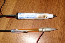
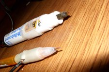
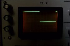
Did anyone say pix? Here you go. The former mechanical pencil now houses the 1x probe while the marker is the 10x. As you can see there is some slight overshoot on the 10x probe but it disappears when i touch it so i'll leave it like that. And the voltage divider is damn near perfect - the last pic is with DC coupling, 2kHz signal set to 6 volts, vertical scale 0.2v/div. The waveform goes over the last division by just a little bit. Given that ripple isn't that steady anyway, this isn't likely to cause any significant errors in my measurements.
Oh yeah and you might ask about the ground clips. The clips i had were too cumbersome to use so i removed them, i'll go buy some proper alligator clips.
Hmm so you say nothing must be grounded... With the amount of interference here (there's a stepdown transformer right outside) i don't know how i could pull that out and still get stable readings. Like AndrewT said, can't i just get away with the scope earthed and the equipment under test isolated?
Attachments

At first i was contemplating buying a new 16MHz scope. Right now i am VERY glad i bought this instead.
I powered up my boost converter (it's meant to be a one transistor 12 -> 200ish Vdc converter controlled by a 555 timer). I know that by design it won't deliver much power as a very high duty cycle is required and the 555 isn't much of a PWM controller, but the best i got after winding many inductors is 75 volts with just 15 watts load, this is very bad. Efficiency isn't stellar either at 65% under 5W load dropping to 55% with 15W, with most of the heat being dissipated in the IRF630B mosfet. The IRF840 i used to have in there was even worse.
So armed with my new 10x probe i started checking things. Gate drive looks okay. When i got to the drain, things got ugly. I immediately noticed HUGE ringing even with no load. With the load connected, things started getting clearer. There is about 150Vp-p of high frequency ringing - that is DOUBLE the DC value i am getting, and roughly where my DC output *should* have been.
Alright that's where the bandwidth comes into play. Zooming in, the ringing is at ~48MHz. I didn't know i had built a radio transmitter instead of a power supply! 😱 The second problem is the small output capacitor (100uF), so most of this stuff gets to the output too. So next week i'll be playing with snubbers and output LC filters. 😉
Using a 'scope opens up a whole new world 😉
The probes look good... much better than coax and crocs.
The probes look good... much better than coax and crocs.
Thanks, i did my best. Still have to secure the tips a bit better and make them pointy, but other than that they do great.
I think i have figured out pretty much all the controls. There are a few trimmers that i have NO IDEA as to what they do, but i think it's a good idea not to touch them.
Oh don't touch those trimmers. Those are for launching the nuclear missiles.
Mmm nuclear missiles. Okay, i'll think twice before deciding to use them...
Anyway back to my little 555 boost circuit. I realized one important thing - there isn't much use messing around with it. I don't have a need for this circuit (apart from charging caps where it does fine in its current form), and i don't have a stable 12 volt supply to begin with. Powering a SMPS with another SMPS isn't too great of an idea.
My guess atm is that the ringing has little to do with the effects i'm seeing. The circuit simply runs out of duty cycle when asked to drive more than a few milliamps hence the huge voltage drop. Also in the long term the voltage keeps dropping slowly as the MOSFET gets hotter, clearly due to increasing RDSon because nothing changes in the waveform, and the voltage comes back up if i point a fan at the mosfet.
Also, the ringing actually comes from the gate drive itself, when the fet is switched off, and what i see on the voltage waveform of the fet is just a magnified version of that. It looks like driver transistors are needed with the 555. But my guess is that removing the ringing would only reduce heating and increase efficiency, it won't keep the voltage from dropping. If i would be doing this seriously i'd use 3 stages in the converter, so that duty cycle never exceeds 70% for any stage. This should be able to deliver some current.
Right now i'll be starting a different boost converter circuit, i'll be trying to get 12v @ 100mA out of a 3.7v Li-Ion cell. I have some mosfets recovered from a motherboard that have RDS of 3.2mOhms. Compared to the 400mOhms of the IRF630B they should be fairly efficient. 😉
Last edited:
- Status
- Not open for further replies.
- Home
- Design & Build
- Equipment & Tools
- Quick scope probe question