I just bought myself a Russian analog scope model C1-71, for $117. The seller ran it thru the full set of tests with a function generator and it seems it can handle up to 200MHz. But he did not give me a probe along with the scope.
Taking a quick look online i spotted a 200MHz probe for $20 which seems fine to me and i thought about ordering that, since in my local stores the prices are higher. That probe is going to take about a week to arrive and out of curiosity i tried using a plain piece of 75-ohm TV coax about a meter long. The self-calibration wave looks perfectly square, but its frequency is just 2kHz so it could be a bit off in the MHz range... but i don't really need that, i bought the thing mainly for amplifier and SMPS work. I do have a certain project involving 133MHz but that's to come in the next months.
So, the question is, can i use the plain coax for basic audio frequency measurements? The scope itself can handle up to 60 volts input so i am gonna need the 10x probe for offline SMPS work anyway, but till it arrives can i just use this cable for low voltage testing? It's designed to carry UHF TV signal anyway. 🙂
Yes you can make measurments and check signals with a piece of coax. You might consider using a high voltage cap in line with the coax. There is a specification for the maximum input voltage for the scope. If you excede that while measuring the plate voltage for instance, it could be very bad. Like a 400-500v in the low microfarad range. 🙂
Thanks for the heads up. I'll buy a BNC connector and an alligator clip tomorrow to go with the cable and make this a "proper" hack. I already have a probe tip from my old multimeter. 🙂
The scope does have an AC coupled mode so the input capacitor is built-in, but i do not know its voltage rating so it's best to play safe (its voltage rating isn't mentioned in the scope's schematics either), i'll do like you say. 4.7uF at 400v sounds fine?
The scope does have an AC coupled mode so the input capacitor is built-in, but i do not know its voltage rating so it's best to play safe (its voltage rating isn't mentioned in the scope's schematics either), i'll do like you say. 4.7uF at 400v sounds fine?
Sorry for double posting, i can't edit anymore. I just did my first SMPS ripple/noise test. 🙂 I used my trusty old 200W Seasonic ATX power supply, which i use as a general purpose/bench supply because it's very stable. 5v ripple clocks in at about 30mV, with 12v at 60mV. I checked Hardware Secrets and those are quite respectable numbers especially for a supply this old, never recapped, never even opened. 🙂
I'm still getting used to reading the divisions but the frequency the supply is operating at looks to be roughly 90kHz. The sync circuitry of the scope is a little bit unstable, but maybe it's because some higher frequency noise is also present in this power supply. In any case it's usable, and WAY better than nothing.
I'm still getting used to reading the divisions but the frequency the supply is operating at looks to be roughly 90kHz. The sync circuitry of the scope is a little bit unstable, but maybe it's because some higher frequency noise is also present in this power supply. In any case it's usable, and WAY better than nothing.
Divider probes (or times 10 probes as everyone call them) offer a low input capacitance of only a few PF. Using one of these is where you use the low freq "cal" signal to adjust the trimmer on the probe for a flat squarewave with no "tilt" on the tops/bottom.
A coax lead will load the circuit capacitively, which for most low impedance audio stuff isn't to important. It also loads the circuit with the input impedance of the 'scope usually 1 meg ohm, the probe raises this to 10 meg ohm.
A coax lead will load the circuit capacitively, which for most low impedance audio stuff isn't to important. It also loads the circuit with the input impedance of the 'scope usually 1 meg ohm, the probe raises this to 10 meg ohm.
I'm still getting used to reading the divisions but the frequency the supply is operating at looks to be roughly 90kHz. The sync circuitry of the scope is a little bit unstable, but maybe it's because some higher frequency noise is also present in this power supply. In any case it's usable, and WAY better than nothing.
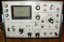
Look for an "hf reject" in the triggering options. Post a picture of the front panel 🙂
Look for an "hf reject" in the triggering options. Post a picture of the front panel 🙂
Here's the pic... And here's for hoping that you can read Russian. 😀 I can only read like half the stuff myself. The very bright camera flash drowned out both that and the trace, but the screen is actually backlit by two glorious yellow bulbs. And it's adjustable too, from "nothing" to "barely enough" 🙂
The little knob on top of the volts/div selector (they do like dual pots don't they), has a rather major effect on sync stability. Turning it to the left = better sync and much clearer trace, but nothing comes for free and it happens to also attenuate the signal, thus the volts/div ratio changes and it's not possible to estimate the signal voltage anymore. I have no idea what that knob is actually for, but when turned fully to the right it also clicks, it seems to have a switch built-in.
Edit: There's a similar one on the time section and i just noticed they both read "Calib." which is definitely short for calibration, and their behavior confirms that they are fine tuning for the main switch. I still don't understand why the one on the volts/div switch makes the trace more stable.
Attachments
Last edited:
Sounds like that knob with the detent is the timebase veriner, to measure frequency this needs to be in the "clicked" position, otherwise adjust to best result.
Bob
Bob
Sounds like that knob with the detent is the timebase veriner, to measure frequency this needs to be in the "clicked" position, otherwise adjust to best result.
Bob
Ah, vernier. This term sounds familiar. So defeat them for measuring frequency/voltage, or tweak if all i need is a good look at the waveform. Gotcha.
the AC/DC cap is feeding 1M input impedance.
You don't need 4uF as it would have F-3dB~0.03Hz.
Even 470nF would be F-3dB ~ 0.3Hz and F-1dB ~ 0.6Hz.
That's still very wide for an AC input.
Look for a 630Vdc (400Vac) or 1000Vdc (600Vac) input cap in a value getting up around 100nF if you intend replacing the existing input capacitor. 100nF & 1M0, F-1dB ~ 3Hz.
the AC/DC cap is feeding 1M input impedance.
You don't need 4uF as it would have F-3dB~0.03Hz.
Even 470nF would be F-3dB ~ 0.3Hz and F-1dB ~ 0.6Hz.
That's still very wide for an AC input.
Look for a 630Vdc (400Vac) or 1000Vdc (600Vac) input cap in a value getting up around 100nF if you intend replacing the existing input capacitor. 100nF & 1M0, F-1dB ~ 3Hz.
True, i forgot about the 1Megohm resistor, you're right about the frequency. The existing cap is specified as 0.022uF so that makes 22nF... So the current -3dB frequency comes out as 7.2Hz. That's a bit high for my taste honestly. I'll take your advice and replace it with a 100nF/630Vdc one. I could not find a 1kV part around with this capacity so 630V will have to do.
Look for an "hf reject" in the triggering options. Post a picture of the front panel 🙂
😉 Wish I hadn't asked lol
At a guess,
Top right controls look like trigger level (the knob with -/+). That control should adjust the point on the waveform it triggers.
Is that a dual pot ? if so might have a "trigger delay" action too.
The top switch is AC or DC coupling for the trigger signal... maybe 😉
The one below is pos or neg trigger.
The four position switch... might be something like "normal", "HF reject", then external trigger with a 1 or 10 divider for use with the socket at the right.
To check the calibration of the vertical (volts) axis use a DC PSU and DVM. Easy and accurate.
Top right controls look like trigger level (the knob with -/+). That control should adjust the point on the waveform it triggers.
Is that a dual pot ? if so might have a "trigger delay" action too.
Yes it is a dual pot. I don't really know what the knob at the top does though, but if i were to judge by the others it would be a fine trigger level control. I use it when the waveform doesn't sync no matter where i turn the main trigger knob and it stabilizes the trace. I don't actually know what a trigger delay is supposed to do so please explain. 🙂
The top switch is AC or DC coupling for the trigger signal... maybe 😉
The one below is pos or neg trigger.
Yeah i think i figured those out... Positive trigger = trigger on rising edge, and negative = trigger on falling edge, right?
The four position switch... might be something like "normal", "HF reject", then external trigger with a 1 or 10 divider for use with the socket at the right.
The first position i am quite sure is "normal" mode and the last two are for the external trigger. The second position reads "on mains" so i'm quite sure it will cause the scope to trigger on the 50Hz mains waveform. I'll try the external trigger option and trigger from the PWM controller of the power supply under test, this should give a more steady display.
To check the calibration of the vertical (volts) axis use a DC PSU and DVM. Easy and accurate.
Sure, will do.
Last edited:
I think i have figured out pretty much all the controls. There are a few trimmers that i have NO IDEA as to what they do, but i think it's a good idea not to touch them.
The scope can be triggered in "one shot" mode too by pressing that button pointed to by the mode switch, and it goes kinda like this: Crank the brightness up, hit the button, and hope that you figure out the wave before it disappears. 😛 Not particularly useful.
It's got horizontal hold collapse too, that works very well for finding out peak voltage.
The knob on top of the trigger level one, i still think it's a fine control. Though i found nothing conclusive by using it on the internal calibration signal, it did well at stabilizing the trace when i was measuring ripple of that switching PSU.
The calibrator seems to be able to also output DC voltages besides that 2kHz signal, but that doesn't work too well. However there's no reason why an external source and a DMM can't be used instead, just like Mooly said.
Maybe any russian speaking people are able to decypher the text on the trimmers, as i can't figure out myself and i don't feel like turning them to see what they do.
Attachments

Delayed trigger... probably not using the correct term here (just to confuse you), is it trigger holdoff ? simply delays the "pulse" that the trigger circuit generates that is used to start the sweep. It's useful for getting stable triggering on unstable input signals that are perhaps not periodic such as sine/square etc.
Don't confuse it with delayed sweep on dual timebase 'scopes which is totally different.
Mains trigger is useful for examining low level ripple as the 'scope is always triggered correctly... much better than using the very low level signal from the Y amp if the ripple is tiny.
Any 'scope should be rock solid on periodic signals, sine square etc.
Delayed trigger... probably not using the correct term here (just to confuse you), is it trigger holdoff ? simply delays the "pulse" that the trigger circuit generates that is used to start the sweep. It's useful for getting stable triggering on unstable input signals that are perhaps not periodic such as sine/square etc.
Thanks, i understand now.
Mains trigger is useful for examining low level ripple as the 'scope is always triggered correctly... much better than using the very low level signal from the Y amp if the ripple is tiny.
Okay, i'll keep that in mind.
Any 'scope should be rock solid on periodic signals, sine square etc.
That it is, like i said the seller tested it up to 200MHz on sinewave. Square wave capability is probably lower (i heard something about -3dB being at 150MHz), but on that 133MHz thing of mine i just need to see if it oscillates, i don't care about the waveform (it's a PLL IC, if it does start up then it's very likely to be stable and outputting the right waveform).
It would be interesting to know what the bandwidth was... 150 mhz ?
I wouldn't like to say, but it's a pretty impressive 'scope that's only -3db down at that.
15mhz would be considered a "good" general purpose 'scope from a few years back.
Interesting 🙂
I wouldn't like to say, but it's a pretty impressive 'scope that's only -3db down at that.
15mhz would be considered a "good" general purpose 'scope from a few years back.
Interesting 🙂
I don't own a function generator (honestly i would have bought one too but not enough mana 😛), but i can check it on the squarewave output of a PLL chip on a PIII mobo, which can be set for 66, 100, 112 and 133MHz. We'll see how square it is...
I found some inspiration here: How to Build Your Own Oscilloscope Probes and How to make a 100X oscilloscope probe - a great resource for How To's from Wikia so i also bought all the stuff i need to build 1x and 10x probes. Read: BNC connectors, 50 ohm coax (my 75ohm stuff was too stiff), a bunch of 1% resistors and a couple trimmers. I'll be posting some pics of the probes i made tomorrow, right now the 10x one is still in the works.
I found some inspiration here: How to Build Your Own Oscilloscope Probes and How to make a 100X oscilloscope probe - a great resource for How To's from Wikia so i also bought all the stuff i need to build 1x and 10x probes. Read: BNC connectors, 50 ohm coax (my 75ohm stuff was too stiff), a bunch of 1% resistors and a couple trimmers. I'll be posting some pics of the probes i made tomorrow, right now the 10x one is still in the works.
for rock solid triggering use as much as possible external triger input. Internal triggering will change when the input amplitude changes, ie when you move the probe from point to test point. External will also require another scope probe though. Bought 2 I hope? You connect the external trigger probe and test probe to the same point, adj your trigger levels etc now when you move from test point to test point your scope will always be triggered.
for rock solid triggering use as much as possible external triger input. Internal triggering will change when the input amplitude changes, ie when you move the probe from point to test point. External will also require another scope probe though. Bought 2 I hope?
I bought not 2, but 3 BNC connectors, 5m of cable, and i have enough tips and old pens available... 😀 I completed 100% my first 1x probe, by the 2nd schematic here, the one with the 10kOhm resistor in series. Complete with ground clip and all. 🙂 I'll post a pic tomorrow.
A major change i see with this compared to the plain 75ohm coax is that i see FAR less high freq noise on the power supply output, maybe that cable was picking it from somewhere. The waveform also bounces quite a bit vertically, it didn't use to do that. But i set it to "normal" trigger and set the trigger level to the point where the waveform nearly disappears and it stops bouncing. It flickers a bit, but it's stable enough to be able to take a good look at the ripple. Ripple on that PSU is at the same level that it was on the first measurements, so nothing changed in the power supply, i guess the noise wasn't coming from it. I'll try to use external trigger tomorrow.
Anyway i'm really happy with this probe i built, have to finish the 10x one so i can have fun in that boost converter i made a few months ago. I never managed to get more than 15W from it and under load its voltage drops like a stone.
- Status
- Not open for further replies.
- Home
- Design & Build
- Equipment & Tools
- Quick scope probe question