What is your motivation for giving away free PCB-s? Self promotion? Advertising?I can send you the PCB if you pay me the shipping fee. However, what I developed currently is the integrated amp product.
Or you simply like DIY audio members?
What is your motivation for giving away free PCB-s? Self promotion? Advertising?
Or you simply like DIY audio members?
Free gifts are limited,After all my money is limited,I am just a DIY enthusiast,But I hope that make more friends,HIFI with more friends to share my results.
Last edited:
COOL
So far i have only built lm3886 amps.
At some stage i would love to built a classic crazy amplifier like this.
How much for a stereo pair shipment to south africa?
So far i have only built lm3886 amps.
At some stage i would love to built a classic crazy amplifier like this.
How much for a stereo pair shipment to south africa?
Now under development, to pass the test, I will contact you, thank you for your support! Continue to focus on, and I'll have pictures broadcast throughout the process.
this thread will be of interest...
Original Krell Thread
Dead link but I "think" you were referring to this one:
http://www.diyaudio.com/forums/solid-state/31077-krell-ksa-50-pcb.html
this thread will be of interest...
Original Krell Thread
Are you referring to the circuit can be compatible.
Hi gxcabin
give us a bit more info on your design
what sizes in uF for the 4 capacitors?
voltage rails in volts?
what size toroidal
i am a bit worried about the two bridge rectifier sizes ,aren't they a tad small ?
give us a bit more info on your design
what sizes in uF for the 4 capacitors?
voltage rails in volts?
what size toroidal
i am a bit worried about the two bridge rectifier sizes ,aren't they a tad small ?
Hi gxcabin
give us a bit more info on your design
what sizes in uF for the 4 capacitors?
voltage rails in volts?
what size toroidal
i am a bit worried about the two bridge rectifier sizes ,aren't they a tad small ?
Thank you for your question,
1, filter capacitor use BC of 6800UF/63V (6800UF * 4)and is compatible with all kinds of capacitors
2, the design supply voltage is AC32V (0-32V 0-32V) 1 channel
3, this design does not intend to use the toroidal transformer,Will use 1000 watts's EI type transformer,EI transformers with small filter capacitor combination, I think it is perfect.
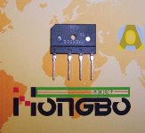
4, rectifier bridge volume small, but each reached 35A, one PCB use two.
wow . I didn't know you got 35A in that package type.
I will probably run larger capacitance and the bridge rectifiers off board anyway.
I like big toroidal with big filter capacitance with this amount of current. I will probably use 800va with 60000uF or more per voltage rail for each channel. Personal preference 🙂
more questions:
1)Which devices do you tend to use for final stage? I see you made provision for 2 pairs on the pcb.
2)have you done some calculations on what bias current you are going to set up?
Sorry for all the questions. Just curious about your specific design.
I will have more questions 🙂
You're perfectly welcome to ask questions, the key is the level of my bad English, I do not know if many issues to answer in English, sorry!
Ring-type transformer and EI-type transformer is not the same, you can always go to test,Personal preference.EI-type transformer and the ring-type transformers, intermediate frequency, low frequency at which the former was better.
1)Which devices do you tend to use for final stage? I see you made provision for 2 pairs on the pcb.
PCB version published by the last, what kind of device is very flexible and determined by the DIY themselves.
2)have you done some calculations on what bias current you are going to set up?
Test PCB board came out
Standard of English is poor, sorry!
Last edited:

It seems a 500va 2x30v with 40000uF per voltage rail for each channel should do what I want it to do.
It seems a 500va 2x30v with 40000uF per voltage rail for each channel should do what I want it to do.

wow . I didn't know you got 35A in that package type.
The funny part :
A plastic GBU bridge rectifier package has a thermal resistance from junction to case of roughly 9 C/W.
Suppose the diodes inside have a Vf of 1 volt, at full peak current load that translates to 70 W (35A * 2 diodes * 1V)
In free air a GBU package would reach 630C above ambient.

I will use those 35A 400V metal can bridge rectifiers. They are cheap enough ,and makes more sense in the end.
maybe the Chinese count differently as well.The funny part :
A plastic GBU bridge rectifier package has a thermal resistance from junction to case of roughly 9 C/W.
Suppose the diodes inside have a Vf of 1 volt, at full peak current load that translates to 70 W (35A * 2 diodes * 1V)
In free air a GBU package would reach 630C above ambient.
They certainly don't adopt much of our standards.
- Status
- Not open for further replies.
- Home
- Amplifiers
- Solid State
- KSA50 AMP(New production Live in...)