i'm just try to build this thing, absolute no experiance with electronics
What dus 15V means see picture and red circle.

does it mean you have to connect -15V and +15V or what?
does any one has build this project?
do you have an total pcb board?
Thanks,
Harry
What dus 15V means see picture and red circle.
does it mean you have to connect -15V and +15V or what?
does any one has build this project?
do you have an total pcb board?
Thanks,
Harry
Last edited:
Yes you need a separate +- 15V for PGA2310 ( dual voltage ) for analog part .i'm just try to build this thing, absolute no experiance with electronics
What dus 15V means see picture and red circle.
View attachment 174809
does it mean you have to connect -15V and +15V or what?
does any one has build this project?
do you have an total pcb board?
Thanks,
Harry
http://www.diyaudio.com/forums/anal...er-volume-controlers-source-selections-3.html
Vikt0r and Pryanic build this also , in page 3 to 18 will find info , also I have posted my project from 3 years old on perfboard .
I do not have such pcb board for this but maybe Pryanic or Vikt0r will post files for etching that pcb !
Happy diy !
I am recommending to program the last firmware for PGA you find in this thread .
Last edited:
danzup,
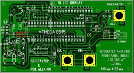
The Power-supply board layout is a little different from from the schematic, Is it still safe to use? (particularly around the mains)
Do you have a board layout that tells me where all the parts go for "IS REV 4 A". the board layout in your first post is for a chip source selector.
And may I ask what this is? (I've also noted that many of the transistors are different in the board layout... Is it safe to follow the schematic?)
Thanks,
Kurtis
Ps. Board layouts are done, They didn't turn out so good but they are usable. Going to tin and flux on Tuesday. I'll post pictures when there something to post of 😛
Attachments
The Power-supply board layout is a little different from from the schematic, Is it still safe to use? (particularly around the mains)
Do you have a board layout that tells me where all the parts go for "IS REV 4 A". the board layout in your first post is for a chip source selector.
And may I ask what this is? (I've also noted that many of the transistors are different in the board layout... Is it safe to follow the schematic?)
Thanks,
Kurtis
Ps. Board layouts are done, They didn't turn out so good but they are usable. Going to tin and flux on Tuesday. I'll post pictures when there something to post of 😛
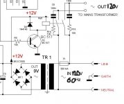
1. yes ! no problems about if you keep in mind that there are live 230V voltage that can kill you !
2. that pcb was made by alexmm from this forum but have been tried by me and they worked .
3. use whatever tranzistors have , just stay with the schematics
4. that is a ferrite 0 ohm wire jumper
We are waiting for your pictures !
Last edited:
dear Danzup,
could you program the filmware for PGA2310 with volume bar..
Thanks
Harry
I will do such in some free time .....
Thanks Danzup
Safe to leave out the zero ohm ferrite jumper then?
Heheh, in Canada we have only have 120VAC 60Hz, still dangerous, still gives a nice buzz if your not carefull.
Does anyone have any recommendations for LCD screens beside the obvous 16x2 lines. Colors and stuff, known models that work well.
Thanks, Kurtis
A piece of wire instead the zero ohm ferrite jumper is ok .Safe to leave out the zero ohm ferrite jumper then?
Heheh, in Canada we have only have 120VAC 60Hz, still dangerous, still gives a nice buzz if your not carefull.
Does anyone have any recommendations for LCD screens beside the obvous 16x2 lines. Colors and stuff, known models that work well.
Thanks, Kurtis
All Lcd compatible with Hitachi HD44780 will do .
On post Nr.3 :3. Control and audio select with relay and r2r volume
- volume with quality MELF resistors for r2r or shunt adjusting
- infrared remote control in the stop / start amplifier
- selection from 4 sources of signal relays
- version Display with LED or LCD display as it wants ( depending on board will possible planting to serve both variants )
Sorry but discover an error on pdf
File Type: pdf sch_supply & relays.pdf (26.1 KB,)
value for resistors R39L , R39R and R38L, R38R are swapped !
the correct value are :
R39L , R39R = 11K
R38L , R38R = 53K
Started putting parts in, pictures soon
I have a quick question,
I'm currently building carlos's blame ST along with this VCSS. I've discovered that each channel pulls 180watt's and 2.5 amps (I am currently building 2 channels) . This part of the schematic here:
What kind of resistor wattage ratings would i need for R14 and R15? And if there's any information i need to know, let me know.
Thanks,
Kurtis
I have a quick question,
I'm currently building carlos's blame ST along with this VCSS. I've discovered that each channel pulls 180watt's and 2.5 amps (I am currently building 2 channels) . This part of the schematic here:
An externally hosted image should be here but it was not working when we last tested it.
What kind of resistor wattage ratings would i need for R14 and R15? And if there's any information i need to know, let me know.
Thanks,
Kurtis
1/2W ( that resistors do not depend on the power of consumer side but there are on circuit together with capacitors to protect the relay contact ) .
Voltage of capacitor >120V I think you know that .
the correct schematics :
Attachments
Last edited:
Dear Danzup,
does your design works also with VFD display's ?
try to build your design but use an VFD display of Futaba
does your design works also with VFD display's ?
try to build your design but use an VFD display of Futaba
Dear Danzup,
I want to learn what you do with the source (BAS files) do you have links
witch editor and compliler i can use to change the BAS source
Regards,
I want to learn what you do with the source (BAS files) do you have links
witch editor and compliler i can use to change the BAS source
Regards,
1.YES !Dear Danzup,
1.
does your design works also with VFD display's ?
try to build your design but use an VFD display of Futaba
2.
I want to learn what you do with the source (BAS files) do you have links
witch editor and compliler i can use to change the BAS source
It is working very well !
2. BASCOM :
download for free here :
Downloads - MCS Electronics
Dear Danzup,
could you also inform me witch remote control can be used
in your project with the PGA
could you also inform me witch remote control can be used
in your project with the PGA
Dear Danzup,
could you also inform me witch remote control can be used
in your project with the PGA
With all my project : all RC5 Philips coded IR remote will work.
Use a universal remote and do a scan on remote till the controller respond to on/off button then that is .
For those that used ever a universal remote know what I am saying here .
Or press from universal remote unit the button : " cable/sat ".
Vol+ ,Vol - ,Ch+ ,Ch- ,power and mute ( for some project pressing buttons 1 to 4 will direct select input 1...4 ).
Do not use remote from : Sony , Technics, Mitsubishi and another japan type as there is known they do not implement RC5 Philips type of encoding .
( Even an Orion tv set ir remote work for me ( !! ) )
look here :
http://i35.tinypic.com/flvm7c.jpg
Danzup,
i can not find the complete file bas and HEX for the project 2 with PGA
thanks
page 2 post #18 - variant with stop at +10dB
page 3 post #25 - variant with stop at +31.5dB
a little reading of thread will reveal you the files but there are not the .hex attached in post#18 and after you install Bascom you must compile this code and then write to Atmel UC .
I will provide the complete files for people who only want to program the Atmel chip with firmware in post #18 without installing Bascom compiler .
In the post #25 there are all files included the .hex in .zip archive .
Last edited:
- Home
- Source & Line
- Analog Line Level
- Yet another Volume controlers and source selections