Hi DX, guys
I see the original DX amp thread visited a bit today. What was the interest?
Also, I get a phone call from the parts supplier today who says: "sorry, but we're outta this, that, that, those and all of them too.......awwwwww!
I see the original DX amp thread visited a bit today. What was the interest?
Also, I get a phone call from the parts supplier today who says: "sorry, but we're outta this, that, that, those and all of them too.......awwwwww!
Man... i would like to say things to you and to my friends..the ones that believes my
skills building amplifiers for so long time as i use to do.
I was poor, and then i had to use what i had from junk..i have learned that transistors are transistors and anything more than transistors...they have not character, personality, empathy, mood, good will or bad will.... they just conduct... a resistance transference.
They have:
Maximum voltage from Colector to emitter
Maximum current of operation, current from colector to emitter
Maximum dissipation of power
They have gain and they have maximum frequency of operation, they are NPN and PNP.... and anything is more important than that.
For the input, use the ones you have that can face 35 volts from colector to emitter... search for complementary ones than can conduct 330 miliamps.. search for the ones can dissipate 300 miliwatts... search for gain bigger than 250 an smaller than 550...JUST THAT!
For the VAS, and also drivers, search for ones can dissipate 5 to 10 watts... ones used as drivers mainly... the ones can face 70 volts from colector to emitter..ones that can have the gain from 50 to 220, the ones can manage to face 200 miliamperes or MORE of current from colector to emitter... the frequency, maximum, can be 10 megahertz to 150 megahertz...JUST THAT!
For the output, search for complementary ones that can dissipate 100 watts..that can face 10 amperes of current from colector to emitter, the ones have gain from 20 to 100, the ones can face 80 volts from colector to emitter...and operation frequency is not so much important as you will operate in 20 Kilohertz and not in the Megahertz band.... and all them can go to Megahertz band..the advantage of fast ones is the slew rate..and this produces a difference, almost non audible for average guys...some golden ears (If this guys really exists) can perceive...i think they pretend these things.
Do not mind and bother...do not let transistor be something that impeach you to move, unless you are searching for reasons to give up facing the first stone in the middle of your way.... jump out... cross the stone.... make a curve and go ahead...the junk you have may be enougth.... there are Zillions of Billions transistors that will work.
Good when transistors are able to face twice your supply voltage..because this way, they should be working near the best linearity.
About to be idiot..i think we all are..me too!
regards,
Carlos
Well, I've got plenty of Motorola BD139s and most typical stuff but no TO264 or even TO3P power stuff no BD140, power resistors. No large electros.
Its not smart using electros out of TVs or monitors because they dry out easy. I have this ESR meter to pick OK ones but I don't have enough close values to do much. Once, I used old parts too. In valve days my father never bought anything new. Real tight, man!
On this new one? I don't feel too convinced about that. Anyway, how am I gonna blow the other guys off the planet unless I use bigger, better eh? Ahahahahahaha!
Used parts are tested parts, veterans...things you can trust
Electrolitic condensers is something we need to have new ones..... but transistors does not turn old and weak..they are always new.
Old ones had leakage and losses of gain.. but this was with the old Germanium ones or Radio frequency units..these covered with ceramic, to 100 watts output in frequencies higher than 100 Megahertz..some of them could operate near 500 Megahertz..these ones had reduce gain when old.
Resistances, sometimes, have increase it's value compared to the label and should be measured.
Television transistors are excelent, in special the ones you have in the tube socket, the R,G and B amplifiers..these ones are excelent for VAS
regards,
Carlos
That's interesting about RF power transistors. I didn't know that. I'm just looking at a few NOS Mitsubishi UHF 2SC1968A drivers and the mains for a 40 W linear amp are round here somewhere too. Silver plated, beautiful strip-line stuff. Also hundreds of good wet tantalums. Too bad they won't suit Blame. LoL
2SC1969, 25W, 16V transistor to 6A, made to operate in the HF band
till maximum of 30 Megahertz, used as output transistor to transceivers, SSB and AM, mainly in the HF Radio Amateur bands... also used to 11 meters band (27 Mhz)for the Citizen Band, putting out 15 watts PEP SSB.
It seems it cannot face the peak to peak voltage we have in these amplifiers..you need 70 volts units... see the datasheet in google and take a good look at capacitance and also VCE max... check it please..i am not sure about your 2SC1968A
73/51
Roger,
Carlos
Last edited:

Volker...You have forum message from me Herr Ekkart
answer the message direct to my email adress, as i want to capture your email adress:
carlos.eugenio1951@yahoo.com
regards,
Carlos
.................................................................
Ian finch...you got a message in the forum direct messenger system.
answer the message direct to my email adress, as i want to capture your email adress:
carlos.eugenio1951@yahoo.com
regards,
Carlos
.................................................................
Ian finch...you got a message in the forum direct messenger system.
Last edited:
Great pic, Volker. Of course, if he was using ES, you would not see the guy -
- only a hole in the wall. LoL
- only a hole in the wall. LoL
...yes, it´s cool.
You want to see?
You do´nt beleve in this??
Hehe, try it out and you will feel it!
what's Ubuntu doin' there, ay? 😉
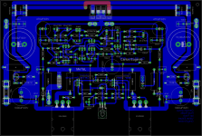
A short status report about the DX Blame PCB - Project:
The board is done (i.e. the EAGLE - .brd - file is completed and approved) and I ordered a prototype from my "etcher" today.
In my eyes the layout is absolutely professional, technically integer and good-looking.
MeTal has done a good job indeed.
I asked MeTal to publish a picture of it.
Maybe he will.
Best regards - have a nice weekend - Rudi_Ratlos
An externally hosted image should be here but it was not working when we last tested it.
It is finally done. I think Rudi has started receiving orders from guys who have not even saw how the PCB will look, I am really surprised 
Attachments
Last edited:
Very nice.... i like it...very good job...just check with Rudi, by
email, something related the names printed.
regards,
Carlos
email, something related the names printed.
regards,
Carlos
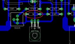
This resistance is 2K, or two 1K resistances in series.
I have asked to create room for 2 resistances in series, to use 2 units of 1K.
Better to avoid a single 2K2, because all instructions of adjustments are based in 2K...so...will confuse all the work previously done.
Do not use 2K2...value is 2K.
Please, fix this as soon as possible, to avoid confusion.
regards,
Carlos
Attachments
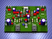
Okay, fixed now. Before we order the PCBs, the green ones, I will have Rudi checking values again, that's no problem.
Attachments
Last edited:
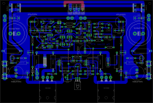
Please, remove this silk screen "MeTal and Carlos Eugenio" from the component side
Let, only, Omar Oash as layout designer and Carlos Mergulhão as Designer in the solder side.
regards,
Carlos
Let, only, Omar Oash as layout designer and Carlos Mergulhão as Designer in the solder side.
regards,
Carlos
Slow down, please!
We are still in the prototype - phase!
No more images at this moment, please!
There are at least 2-3 weeks left to define the final look, review the silkmask, ...
Be happy instead!
The layout is done and approved!
Enjoy the weekend!
Best reagrds - Rudi_Ratlos
We are still in the prototype - phase!
No more images at this moment, please!
There are at least 2-3 weeks left to define the final look, review the silkmask, ...
Be happy instead!
The layout is done and approved!
Enjoy the weekend!
Best reagrds - Rudi_Ratlos
An externally hosted image should be here but it was not working when we last tested it.
Looks great
Shouldnt there be heatsinks on bridge switch diodes ?
And theres still room enough to make rail lines slightly wider, if you take a bit from ground plane
Or do you have a reason not ot ?
Shouldnt there be heatsinks on bridge switch diodes ?
And theres still room enough to make rail lines slightly wider, if you take a bit from ground plane
Or do you have a reason not ot ?
Yes dear Omar..thank you very much you correct that
also i would like to explain what means elegance to me... and elegance is when things apear discreet, not obvious, not flashy, different of a huge illuminated billboard ... Ithink most this way is more decent, thinner, more charming, seems to have more class.
Make our names (Carlos Mergulhao - Designer .... and Omar Oash - layout) the smallest you can..almost same size of the letter you're using into identification numbers for parts and for the values.... everything same size please.
In order to the ones observe the board first time... will not see our names first...they would not be in evidence..not alike a show of promotion and advertising (propaganda) of our names....only the ones really want to know who have made, these guys will be searching for identification and will find our small sized names there.
Please, i have already explained to Rud, and i think we have agreement......try to make these lette,. all them, the same size compared to other letters used to print values and parts numbers, these letters already printed in your layout.
Congratulations, thanks very, very much, i am very satisfied with your good work and i am waiting you, near future, producing the Troyan layout too.
Dx Blame should be printed somewhere..also, same size...not as advertising..just as an information, a reference, to people know the brand, and the ones have worked to produce the amplifier, design and layout.
regards,
Carlos
Last edited:
- Status
- Not open for further replies.
- Home
- Amplifiers
- Solid State
- Dx Blame ES .... based into the Blameless, i am trying a new amplifier