In 2006 Oct, my PP tube power amp, a Mentmore Industries TVA-100, blew one of the KT88 in the left channel leaving only right channel operating. It was the first fault since 1986.
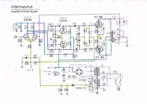
The TVA-100 uses 2 x 12AX7 for input, 2 x 12AT7 for driver and 4 x KT88 for both channels putting out 100W per channel using ultra-linear design. It has a standby switch and external valve bias controls for adjusting and checking bias of the output valves. I don’t have a schematic of the TVA-100. Given that it is the refinement of the TVA-1, I get the TVA-1 schematic as a guide instead. The TVA-1 is about 80% close to the TVA-100 but some components values are different.
The faulty parts were blown, the main fuse 5A 250v, on the left channel, the driver tube 12AT7, the KT88 (V3), the 330R screen grip resistor, the 47R cathode resistor, the 10uf capacitor connecting the cathodes of V3 and V4 and the ageing caps on the driver. The right channel had the 100K-oversized resistor blown but the channel was still working.
Version 1
As the TVA-100 has showed its age, I overhauled the amp with better components while fixing. I replaced the electrolytic and film caps, valve sockets with better grade and all the 0.5w resistors with 1w tantalum. There were 8 oversized resistors used in the circuit, the 100K, 33K x 2 and 6.8K in each channel. I guess they were 5w for the input and driver plate. The leg holes of 100K and 6.8K on the PCB are shorter (guess for 2w size) than the oversized resistors in use. I replaced them with 5w Kiwame. On 2007 New Year’s Day, the amp was back in action.
The first time powered up the amp with the standby switch off, I adjusted the bias of output valve from V1 to V4 using their individual VR. Each VR has a LED above it. When selected the numbered valve and turning up its VR, the LED will light up softly to fully when the meter scale reached to 7+. This is the optimal bias setting point on the meter scale reading. After the first adjustment and half an hour play, the bias of 4 valves needed to be re-checked and re-adjusted to keep them on 7+. I had re-checked the bias during several listening sessions and had not noticed the unstable bias on V4 before moving onto Version 2.
Version 2
a) During the process of fixing up the TVA-100, I had plans to upgrade it with better components. I noticed the oversized 100K and 6.8K resistors have a shorter leg holes on the PCB. They appear the size of 2w. Then I changed the Kiwame 5w and the 330R 5w Dale wirewound screen grip resistors to AN tantalum 2w. The TVA-100 has a soft start circuitry. During this change, I found the 4.7K 10w ceramic wirewound resistor next to the relay switch on the circuit board was burned open with 0 resistance. I replaced it with a Mills MRA 12w wirewound. On the first start up of the Version 2, after playing about 10mins, there was a burnt smelling from the amp. I turned the amp off and found the MRA’s glossy coating turned into matt, a sign of overheating. The resistance is still holding 4.7K. I changed it with a 10w ceramic wirewound. I kept an eye on the amp after power up. About 5mins I could feel the heat from the chassis, the main switch between the bias VR adjustments, the location of the resistor was radiating substantial amount of heat. I shut the amp down and reinstated the original brunt resistor. It should have worked without the 4.7K resistor. I don’t know the high heat generated from the working 4.7K resistor has done something harm to the amp in relation to the following overrun bias on V4.
I started up the amp and adjusted the bias as of Version 1. The V4 bias ran up to 8 within half an hour. I turned the VR down to keep it on 7+ and rechecked the bias every 10 to 15mins, the V4 bias kept running up to 7-1/2 or 8. The V4 bias appeared stable by turning down the VR to 7+ until the VR’s arrow pointed to 10 o’clock while the others were close to 12 o’clock. When the V4 bias reached to 8, the left channel had a boiling water noise masking up the sound. I shut down the amp when the boiling water noise came. If I left the V4 VR setting on 10 o’clock for the next power up, the V4 bias would stay on 3 after an hour playing and kept staying there unless the VR was turned up again. This overrun bias only happens on V4 and does not come with tube. I swapped the V3 to V4 and right to left and also swapped the input and driver tubes from right to left but still in vain. I used the contact clean spray on the VRs hoping to cure any dirty contact.
b) I reverted all the AN 2w resistors back to version 1 also swapped the 10uf cathode caps from right to left. I powered the amp up and initiated the bias adjustments to 7+. After 15mins, the V4 reached 7-1/2+ by turning back to 7+ and the V4 repeated the same in the next 30mins but appeared stable when its VR was on 11 o’clock and the others on 12:00. The V4 bias overrun was less intense than Version 2a. With the VR position on 11:00, the V4 bias was holding up in the range of 7+ to 7++ and lasted to finish 3-4 hours listening session. I had left the V4 bias running to 8, there was no boiling water noise in the left channel. However, I had to reduce the left gain one step down on the pre-amp to keep both channels in balance. If I left the V4 VR at 11 o’clock on the next start up, the V4 reached 4 while the other 3 reached 7+ in a minute. The V4 took an hour to reach 6+ and another half hour to reach 7+.
Version 3
I took vdc measurements on the oversized resistors, the 100K 616v, 33K 550v and 6.8K 260v. I use the formulae I=E/R and P=EI to work out the power dissipation, ie the 100K = 4w, 33K = 9w and 6.8K = 10w. I replaced them with Mills MRA 12w wirewound resistors together with the 330R screen grip resistors.
After this change, the overrun bias on V4 remains similar patent as Version 2b. I let the V4 bias settle on 7+ from the last listening session and all 4 VRs setting are close to 11:30. The V4 bias will take 2 hours from 4 to 7+ in the next listening session. The TVA-100 sounded best after 2 hours play.
I noted the bias behavior of the output valves with the standby switch on / off during the past months.
1) Start up with standby off – The bias on V4 took 2 hours to reach 7+ while the others reached 7+ within 5mins. Turn the standby on after playing 4 hours, within 5mins, the V4 dropped to 1, V3 to 0.8, V2 to 3 and V1 to 4. Their readings remained the same after another hour.
2) Start up with standby on – After 10mins, the V4 moved to 1, V3 to 0.8, V2 to 3 and V1 to 4.5 and they remained the same reading regardless how long the amp was left on (10mins to 5 hours). Turn the standby off after 2 hours, the V4 would reach to 7+ in a min along with the others. The V4 reaching from 4 to 7+ depended on the time the amp was on and the time the standby switch was turned off. The longer the time, the shorter the time for V4 reached to 7+.
In short, the V4 has the stale bias when the bias is on and the V1 and V2 have the residual bias when the bias is off. Only the V3 is normal that was the valve previously blown. Although there is no degradation to the sound with the version 3, I want to know what causes this to happen.
My questions are:
1) What causes the overrun bias on V4 and the residual bias on V1 and V2? Can these be fixed?
2) It is unlikely the VRs at fault given their adjustment are effective. If yes, what is the spec for the replacement and where to find?
3) What is the power wattage of the original oversized resistors used on 100K, 33K and 6.8K? Is my calculation correct on the power wattage?
4) It looks the circuit has no rectification for the heater. Does the TVA-100 use AC for the heater?
5) The 5 rectifiers for HT on the PS board have lost their cathode band marks. I want to replace them with fast recovery diode. What is the recommendation for the replacement?
6) The blown KT88 is one of the last set of my vintage Gold Lion. They have been about 400hrs on. Now I have 3 left. Can I use one pair of the Gold Lion on one channel and a pair of different brand on the other channel?
Here is the link to the relevant pictures and the schematic of TVA-1.
I appreciate very much for your input.
Arron
The TVA-100 uses 2 x 12AX7 for input, 2 x 12AT7 for driver and 4 x KT88 for both channels putting out 100W per channel using ultra-linear design. It has a standby switch and external valve bias controls for adjusting and checking bias of the output valves. I don’t have a schematic of the TVA-100. Given that it is the refinement of the TVA-1, I get the TVA-1 schematic as a guide instead. The TVA-1 is about 80% close to the TVA-100 but some components values are different.
The faulty parts were blown, the main fuse 5A 250v, on the left channel, the driver tube 12AT7, the KT88 (V3), the 330R screen grip resistor, the 47R cathode resistor, the 10uf capacitor connecting the cathodes of V3 and V4 and the ageing caps on the driver. The right channel had the 100K-oversized resistor blown but the channel was still working.
Version 1
As the TVA-100 has showed its age, I overhauled the amp with better components while fixing. I replaced the electrolytic and film caps, valve sockets with better grade and all the 0.5w resistors with 1w tantalum. There were 8 oversized resistors used in the circuit, the 100K, 33K x 2 and 6.8K in each channel. I guess they were 5w for the input and driver plate. The leg holes of 100K and 6.8K on the PCB are shorter (guess for 2w size) than the oversized resistors in use. I replaced them with 5w Kiwame. On 2007 New Year’s Day, the amp was back in action.
The first time powered up the amp with the standby switch off, I adjusted the bias of output valve from V1 to V4 using their individual VR. Each VR has a LED above it. When selected the numbered valve and turning up its VR, the LED will light up softly to fully when the meter scale reached to 7+. This is the optimal bias setting point on the meter scale reading. After the first adjustment and half an hour play, the bias of 4 valves needed to be re-checked and re-adjusted to keep them on 7+. I had re-checked the bias during several listening sessions and had not noticed the unstable bias on V4 before moving onto Version 2.
Version 2
a) During the process of fixing up the TVA-100, I had plans to upgrade it with better components. I noticed the oversized 100K and 6.8K resistors have a shorter leg holes on the PCB. They appear the size of 2w. Then I changed the Kiwame 5w and the 330R 5w Dale wirewound screen grip resistors to AN tantalum 2w. The TVA-100 has a soft start circuitry. During this change, I found the 4.7K 10w ceramic wirewound resistor next to the relay switch on the circuit board was burned open with 0 resistance. I replaced it with a Mills MRA 12w wirewound. On the first start up of the Version 2, after playing about 10mins, there was a burnt smelling from the amp. I turned the amp off and found the MRA’s glossy coating turned into matt, a sign of overheating. The resistance is still holding 4.7K. I changed it with a 10w ceramic wirewound. I kept an eye on the amp after power up. About 5mins I could feel the heat from the chassis, the main switch between the bias VR adjustments, the location of the resistor was radiating substantial amount of heat. I shut the amp down and reinstated the original brunt resistor. It should have worked without the 4.7K resistor. I don’t know the high heat generated from the working 4.7K resistor has done something harm to the amp in relation to the following overrun bias on V4.
I started up the amp and adjusted the bias as of Version 1. The V4 bias ran up to 8 within half an hour. I turned the VR down to keep it on 7+ and rechecked the bias every 10 to 15mins, the V4 bias kept running up to 7-1/2 or 8. The V4 bias appeared stable by turning down the VR to 7+ until the VR’s arrow pointed to 10 o’clock while the others were close to 12 o’clock. When the V4 bias reached to 8, the left channel had a boiling water noise masking up the sound. I shut down the amp when the boiling water noise came. If I left the V4 VR setting on 10 o’clock for the next power up, the V4 bias would stay on 3 after an hour playing and kept staying there unless the VR was turned up again. This overrun bias only happens on V4 and does not come with tube. I swapped the V3 to V4 and right to left and also swapped the input and driver tubes from right to left but still in vain. I used the contact clean spray on the VRs hoping to cure any dirty contact.
b) I reverted all the AN 2w resistors back to version 1 also swapped the 10uf cathode caps from right to left. I powered the amp up and initiated the bias adjustments to 7+. After 15mins, the V4 reached 7-1/2+ by turning back to 7+ and the V4 repeated the same in the next 30mins but appeared stable when its VR was on 11 o’clock and the others on 12:00. The V4 bias overrun was less intense than Version 2a. With the VR position on 11:00, the V4 bias was holding up in the range of 7+ to 7++ and lasted to finish 3-4 hours listening session. I had left the V4 bias running to 8, there was no boiling water noise in the left channel. However, I had to reduce the left gain one step down on the pre-amp to keep both channels in balance. If I left the V4 VR at 11 o’clock on the next start up, the V4 reached 4 while the other 3 reached 7+ in a minute. The V4 took an hour to reach 6+ and another half hour to reach 7+.
Version 3
I took vdc measurements on the oversized resistors, the 100K 616v, 33K 550v and 6.8K 260v. I use the formulae I=E/R and P=EI to work out the power dissipation, ie the 100K = 4w, 33K = 9w and 6.8K = 10w. I replaced them with Mills MRA 12w wirewound resistors together with the 330R screen grip resistors.
After this change, the overrun bias on V4 remains similar patent as Version 2b. I let the V4 bias settle on 7+ from the last listening session and all 4 VRs setting are close to 11:30. The V4 bias will take 2 hours from 4 to 7+ in the next listening session. The TVA-100 sounded best after 2 hours play.
I noted the bias behavior of the output valves with the standby switch on / off during the past months.
1) Start up with standby off – The bias on V4 took 2 hours to reach 7+ while the others reached 7+ within 5mins. Turn the standby on after playing 4 hours, within 5mins, the V4 dropped to 1, V3 to 0.8, V2 to 3 and V1 to 4. Their readings remained the same after another hour.
2) Start up with standby on – After 10mins, the V4 moved to 1, V3 to 0.8, V2 to 3 and V1 to 4.5 and they remained the same reading regardless how long the amp was left on (10mins to 5 hours). Turn the standby off after 2 hours, the V4 would reach to 7+ in a min along with the others. The V4 reaching from 4 to 7+ depended on the time the amp was on and the time the standby switch was turned off. The longer the time, the shorter the time for V4 reached to 7+.
In short, the V4 has the stale bias when the bias is on and the V1 and V2 have the residual bias when the bias is off. Only the V3 is normal that was the valve previously blown. Although there is no degradation to the sound with the version 3, I want to know what causes this to happen.
My questions are:
1) What causes the overrun bias on V4 and the residual bias on V1 and V2? Can these be fixed?
2) It is unlikely the VRs at fault given their adjustment are effective. If yes, what is the spec for the replacement and where to find?
3) What is the power wattage of the original oversized resistors used on 100K, 33K and 6.8K? Is my calculation correct on the power wattage?
4) It looks the circuit has no rectification for the heater. Does the TVA-100 use AC for the heater?
5) The 5 rectifiers for HT on the PS board have lost their cathode band marks. I want to replace them with fast recovery diode. What is the recommendation for the replacement?
6) The blown KT88 is one of the last set of my vintage Gold Lion. They have been about 400hrs on. Now I have 3 left. Can I use one pair of the Gold Lion on one channel and a pair of different brand on the other channel?
Here is the link to the relevant pictures and the schematic of TVA-1.
An externally hosted image should be here but it was not working when we last tested it.
An externally hosted image should be here but it was not working when we last tested it.
An externally hosted image should be here but it was not working when we last tested it.
An externally hosted image should be here but it was not working when we last tested it.
An externally hosted image should be here but it was not working when we last tested it.
An externally hosted image should be here but it was not working when we last tested it.
An externally hosted image should be here but it was not working when we last tested it.
An externally hosted image should be here but it was not working when we last tested it.
An externally hosted image should be here but it was not working when we last tested it.
An externally hosted image should be here but it was not working when we last tested it.
I appreciate very much for your input.
Arron
Hi Arron
Replace the 47µ cap at the VR4 bias-pot, if there are any caps like the TVA-1 has.
Also check the softstart-relay, can you hear the "click" ?
Your amp may not power up completely causing unstable voltages and the "boiling water noise"
Cheers, Klaus
Replace the 47µ cap at the VR4 bias-pot, if there are any caps like the TVA-1 has.
Also check the softstart-relay, can you hear the "click" ?
Your amp may not power up completely causing unstable voltages and the "boiling water noise"
Cheers, Klaus
Another component to verify is the meter selector.
I would not use that plastic Lorlin switch in a tube amp of this category.
It will give you wrong readings on the meter when its worn-out.
You did spend a lot of work+money to the components in the audio section......
- for a safe running the bias circuit is the place to invest -.
I would not use that plastic Lorlin switch in a tube amp of this category.
It will give you wrong readings on the meter when its worn-out.
You did spend a lot of work+money to the components in the audio section......
- for a safe running the bias circuit is the place to invest -.
Hi Klaus
Thank you for your input.
With the use of higher wattage to the plate resistors, the “boiling water noise” was gone. It was due to my wrongly use of lower wattage to these resistors. I have no idea the soft-start relay is functioning properly. But I am certain, the performance of TVA-100 was giving me a sense of stability and reliability for the past 20 years and now it continues to shine through from its sonic improvements.
At the beginning, the prime suspects were the VRs and the meter. As all the biases reading use the same meter and the meter gives the correct bias reading of each valve. So, I have to eliminate them from the list. I have replaced most of the parts that I could find and still there are parts that are not easy to find a replacement. Without the schematic, the precise nature of the circuit is beyond my understanding.
Arron
In 2006 Oct, my PP tube power amp, a Mentmore Industries TVA-100, blew one of the KT88 in the left channel leaving only right channel operating. It was the first fault since 1986.
The TVA-100 uses 2 x 12AX7 for input, 2 x 12AT7 for driver and 4 x KT88 for both channels putting out 100W per channel using ultra-linear design. It has a standby switch and external valve bias controls for adjusting and checking bias of the output valves. I don’t have a schematic of the TVA-100. Given that it is the refinement of the TVA-1, I get the TVA-1 schematic as a guide instead. The TVA-1 is about 80% close to the TVA-100 but some components values are different.
The faulty parts were blown, the main fuse 5A 250v, on the left channel, the driver tube 12AT7, the KT88 (V3), the 330R screen grip resistor, the 47R cathode resistor, the 10uf capacitor connecting the cathodes of V3 and V4 and the ageing caps on the driver. The right channel had the 100K-oversized resistor blown but the channel was still working.
Version 1
As the TVA-100 has showed its age, I overhauled the amp with better components while fixing. I replaced the electrolytic and film caps, valve sockets with better grade and all the 0.5w resistors with 1w tantalum. There were 8 oversized resistors used in the circuit, the 100K, 33K x 2 and 6.8K in each channel. I guess they were 5w for the input and driver plate. The leg holes of 100K and 6.8K on the PCB are shorter (guess for 2w size) than the oversized resistors in use. I replaced them with 5w Kiwame. On 2007 New Year’s Day, the amp was back in action.
The first time powered up the amp with the standby switch off, I adjusted the bias of output valve from V1 to V4 using their individual VR. Each VR has a LED above it. When selected the numbered valve and turning up its VR, the LED will light up softly to fully when the meter scale reached to 7+. This is the optimal bias setting point on the meter scale reading. After the first adjustment and half an hour play, the bias of 4 valves needed to be re-checked and re-adjusted to keep them on 7+. I had re-checked the bias during several listening sessions and had not noticed the unstable bias on V4 before moving onto Version 2.
Version 2
a) During the process of fixing up the TVA-100, I had plans to upgrade it with better components. I noticed the oversized 100K and 6.8K resistors have a shorter leg holes on the PCB. They appear the size of 2w. Then I changed the Kiwame 5w and the 330R 5w Dale wirewound screen grip resistors to AN tantalum 2w. The TVA-100 has a soft start circuitry. During this change, I found the 4.7K 10w ceramic wirewound resistor next to the relay switch on the circuit board was burned open with 0 resistance. I replaced it with a Mills MRA 12w wirewound. On the first start up of the Version 2, after playing about 10mins, there was a burnt smelling from the amp. I turned the amp off and found the MRA’s glossy coating turned into matt, a sign of overheating. The resistance is still holding 4.7K. I changed it with a 10w ceramic wirewound. I kept an eye on the amp after power up. About 5mins I could feel the heat from the chassis, the main switch between the bias VR adjustments, the location of the resistor was radiating substantial amount of heat. I shut the amp down and reinstated the original brunt resistor. It should have worked without the 4.7K resistor. I don’t know the high heat generated from the working 4.7K resistor has done something harm to the amp in relation to the following overrun bias on V4.
I started up the amp and adjusted the bias as of Version 1. The V4 bias ran up to 8 within half an hour. I turned the VR down to keep it on 7+ and rechecked the bias every 10 to 15mins, the V4 bias kept running up to 7-1/2 or 8. The V4 bias appeared stable by turning down the VR to 7+ until the VR’s arrow pointed to 10 o’clock while the others were close to 12 o’clock. When the V4 bias reached to 8, the left channel had a boiling water noise masking up the sound. I shut down the amp when the boiling water noise came. If I left the V4 VR setting on 10 o’clock for the next power up, the V4 bias would stay on 3 after an hour playing and kept staying there unless the VR was turned up again. This overrun bias only happens on V4 and does not come with tube. I swapped the V3 to V4 and right to left and also swapped the input and driver tubes from right to left but still in vain. I used the contact clean spray on the VRs hoping to cure any dirty contact.
b) I reverted all the AN 2w resistors back to version 1 also swapped the 10uf cathode caps from right to left. I powered the amp up and initiated the bias adjustments to 7+. After 15mins, the V4 reached 7-1/2+ by turning back to 7+ and the V4 repeated the same in the next 30mins but appeared stable when its VR was on 11 o’clock and the others on 12:00. The V4 bias overrun was less intense than Version 2a. With the VR position on 11:00, the V4 bias was holding up in the range of 7+ to 7++ and lasted to finish 3-4 hours listening session. I had left the V4 bias running to 8, there was no boiling water noise in the left channel. However, I had to reduce the left gain one step down on the pre-amp to keep both channels in balance. If I left the V4 VR at 11 o’clock on the next start up, the V4 reached 4 while the other 3 reached 7+ in a minute. The V4 took an hour to reach 6+ and another half hour to reach 7+.
Version 3
I took vdc measurements on the oversized resistors, the 100K 616v, 33K 550v and 6.8K 260v. I use the formulae I=E/R and P=EI to work out the power dissipation, ie the 100K = 4w, 33K = 9w and 6.8K = 10w. I replaced them with Mills MRA 12w wirewound resistors together with the 330R screen grip resistors.
After this change, the overrun bias on V4 remains similar patent as Version 2b. I let the V4 bias settle on 7+ from the last listening session and all 4 VRs setting are close to 11:30. The V4 bias will take 2 hours from 4 to 7+ in the next listening session. The TVA-100 sounded best after 2 hours play.
I noted the bias behavior of the output valves with the standby switch on / off during the past months.
1) Start up with standby off – The bias on V4 took 2 hours to reach 7+ while the others reached 7+ within 5mins. Turn the standby on after playing 4 hours, within 5mins, the V4 dropped to 1, V3 to 0.8, V2 to 3 and V1 to 4. Their readings remained the same after another hour.
2) Start up with standby on – After 10mins, the V4 moved to 1, V3 to 0.8, V2 to 3 and V1 to 4.5 and they remained the same reading regardless how long the amp was left on (10mins to 5 hours). Turn the standby off after 2 hours, the V4 would reach to 7+ in a min along with the others. The V4 reaching from 4 to 7+ depended on the time the amp was on and the time the standby switch was turned off. The longer the time, the shorter the time for V4 reached to 7+.
In short, the V4 has the stale bias when the bias is on and the V1 and V2 have the residual bias when the bias is off. Only the V3 is normal that was the valve previously blown. Although there is no degradation to the sound with the version 3, I want to know what causes this to happen.
My questions are:
1) What causes the overrun bias on V4 and the residual bias on V1 and V2? Can these be fixed?
2) It is unlikely the VRs at fault given their adjustment are effective. If yes, what is the spec for the replacement and where to find?
3) What is the power wattage of the original oversized resistors used on 100K, 33K and 6.8K? Is my calculation correct on the power wattage?
4) It looks the circuit has no rectification for the heater. Does the TVA-100 use AC for the heater?
5) The 5 rectifiers for HT on the PS board have lost their cathode band marks. I want to replace them with fast recovery diode. What is the recommendation for the replacement?
6) The blown KT88 is one of the last set of my vintage Gold Lion. They have been about 400hrs on. Now I have 3 left. Can I use one pair of the Gold Lion on one channel and a pair of different brand on the other channel?
Here is the link to the relevant pictures and the schematic of TVA-1.
An externally hosted image should be here but it was not working when we last tested it.An externally hosted image should be here but it was not working when we last tested it.An externally hosted image should be here but it was not working when we last tested it.An externally hosted image should be here but it was not working when we last tested it.An externally hosted image should be here but it was not working when we last tested it.An externally hosted image should be here but it was not working when we last tested it.An externally hosted image should be here but it was not working when we last tested it.An externally hosted image should be here but it was not working when we last tested it.An externally hosted image should be here but it was not working when we last tested it.An externally hosted image should be here but it was not working when we last tested it.
I appreciate very much for your input.
Arron
Hi SKlau,
As I have bought the Michaelson & Austin TVA-1 serial number 553 , I would very much like to have the pictures of your TVA-100 from Mentmore. The pictures on this thread is not possible for me to load. I have some amateur site related to valveamplifiers at :
Michaelson and Austin
Hobe that you still got the pictures.
Kind regards
Kim
Hi Kim,
I'll send you the pictures to your email address if you require.
The overrun bias on V4 was caused by a DC leakage of the 0.47uf coupling capacitor. After it blew the KT88 of V4 and found the cause. With parts upgraded to the better components, the TVA-100's sonic performance has reached another high level.
Arron
Hi Kim,
I'll send you the pictures to your email address if you require.
The overrun bias on V4 was caused by a DC leakage of the 0.47uf coupling capacitor. After it blew the KT88 of V4 and found the cause. With parts upgraded to the better components, the TVA-100's sonic performance has reached another high level.
Arron
Hi,
Sorry - I did not see your message erlier.
I would like to get the pictures of your TVA-100 including the circuit. I am very curious whether the bias resistor of approx. 220K - before the gridstop resistor of approx. 2K2 to 10K for the KT88's has been changed to 100K on the TVA-100 version!
Good for you that the amplifier sounds well again!!!
Rgds.
Kim
Hi Kim,
I don't have the schematic of the TVA-100. The attached circuitry is the trace from the TVA-100 based on the schematic of the TVA-1. The circuit maybe not complete but the parts values are the TVA-100.
Arron
I don't have the schematic of the TVA-100. The attached circuitry is the trace from the TVA-100 based on the schematic of the TVA-1. The circuit maybe not complete but the parts values are the TVA-100.
Arron
Attachments
Hi Kim,
I don't have the schematic of the TVA-100. The attached circuitry is the trace from the TVA-100 based on the schematic of the TVA-1. The circuit maybe not complete but the parts values are the TVA-100.
Arron
Hi Arron,
Thanks for your reply.
First of all - it's a heavy modification on the TVA-100 if my eyes don't cheat on me.
It seems as if the four pots for the negative bias has been removed. I you look at the schematic drawing of yours, if believe that the bias circuit can't work this way.
The approx - 150 Vdc goes through the two 22k resistors and to ground. I my opinion the minus voltage should go to the negative pole of the 47uF capasitor and then through the 200K resistor to the 2K2 grid stop resistor. Just to have approx -55 to -65Vdc for the KT88 grids?
Working with the TVA-1 nr. 553 I have experienced from a good friend of mine, that the bias circuit should be changed from the 200K on your schematic to 100K and that the pot should be 20K with a 39K to ground. Still keeping the 47uF after the pots.
The reason is that only the old MOV KT88 (GEC) could handle the approx 340K messured from the grid to ground without running with the bias. All the KT88 reissues requires that the approx messured resistance from grid to ground don't exceed approx 150K.
Perhaps this is the explanation why several TVA-1 amplifiers some times went up in flames by use of KT88 reissues. The quality of todays KT88's simply can't match the original MOV KT88.
Tim De Paravicini's TVA-1 was designed and based on MOV KT88.
TVA-1 = Tim's Valve Amp no. 1 (according Mr. Colin, UK distributor)
Please find a small part about the TVA-1 no. 553 on:
leakstereo20
I think that you may have to redraw the schematic of your beautiful TVA-100 amplifier. The sound of these Partridge outputtransformers is quite unike IMO.
Please write back if I have got somthing wrong.
Best rgds
Kim
Hi Km,
I don’t have the technical knowledge how the TVA-100 works. It has been with me since 1986. Its performance always gives me a sense of stability and reliability. It sounded the best with the original Gold Line KT88 but is not critical using the Chinese or the Russian KT88. I rebuilt this amp when it had a problem in 2006 and replaced all the aging parts.
The Mentmore TVA-100 is the refinement of the M&A TVA-1 and used the modern transformer techniques. It would be beyond my knowledge to redraw the schematic of the TVA-100 for it has the external valves bias controls, a stand-by facility and a soft start circuitry.
Arron
Hi Km,
I don’t have the technical knowledge how the TVA-100 works. It has been with me since 1986. Its performance always gives me a sense of stability and reliability. It sounded the best with the original Gold Line KT88 but is not critical using the Chinese or the Russian KT88. I rebuilt this amp when it had a problem in 2006 and replaced all the aging parts.
The Mentmore TVA-100 is the refinement of the M&A TVA-1 and used the modern transformer techniques. It would be beyond my knowledge to redraw the schematic of the TVA-100 for it has the external valves bias controls, a stand-by facility and a soft start circuitry.
Arron
Hi Arron,
Thank you for writing back.
I am not a professional engineer either. 30 years ago I went to the Danish Tecnical Library of engineers and found a lot of old dusty literature in the basement about valveamplifiers. I took me some years just to understand a part of how valveamplifiers works.
As for the Mentmore TVA-100 amplifier a lot of people would like to see the real schematic including myself.
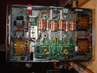
Out from the attached TVA-100 bottom picture from you, I quite understand that it is difficult to make an exact schematic drawing.
When you say that the TVA-100 has external bias control, does it mean that it is possible to adjust the bias from the outside of the amplifier? - with rheostats/potentiometers?
I really would like to see how they solved the soft start circuitry problem. - Well one day I may be lucky to find the Mentmore TVA-100 schematic - who knows.
Thanks for spending your time on this.
Best rgds.
Kim
Hi Kim,
I have documented the trace and drawings of the TVA-100 circuitry. Hopefully I could post the full schematic of the TVA-100 in this forum when I could fully understand how it works.
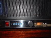
The TVA-100 has an external valve bias controls that can be adjusted each individual valve to achieve optimum performance. The picture shows the correct bias when bias meter reaches above 7 and the LED of the selected valve is light up fully.
Arron
I have documented the trace and drawings of the TVA-100 circuitry. Hopefully I could post the full schematic of the TVA-100 in this forum when I could fully understand how it works.
The TVA-100 has an external valve bias controls that can be adjusted each individual valve to achieve optimum performance. The picture shows the correct bias when bias meter reaches above 7 and the LED of the selected valve is light up fully.
Arron
Attachments
Hi Kim,
I have documented the trace and drawings of the TVA-100 circuitry. Hopefully I could post the full schematic of the TVA-100 in this forum when I could fully understand how it works.
The TVA-100 has an external valve bias controls that can be adjusted each individual valve to achieve optimum performance. The picture shows the correct bias when bias meter reaches above 7 and the LED of the selected valve is light up fully.
Arron
Hi Arron,
Oh - thats a nice picture of your TVA-100.
This feature with the four front pots, switch and voltmeter makes it easy to adjust the bias for each OP-valve.
When I looked the first time inside my TVA-1 and saw the "birdsnest" of wires and odd components never used by M&A, I thought - what is it I have bought?
But after a while and a studio of the bias and driverboard I began to make a drawing of the amplifier - component by component. ( got some start help from another entusiast here.)
Up untill now I have copied the bias-board, and I am about to reproduce the driver-board as well.
On my amateur homepage mentioned erlier you can see a bias-board for the TVA-1 almost similar to the bias-board inside your TVA-100. Some of the components may be different, but it is possible to copy the bias-board after the PCB messurements I have made.
When I have the complete PCB-copy of the entire TVA-1 it should be possible to make a "new" Michaelson & Austin amplifier clone ( exept from the OP's).
Note that the bias resistors has been changed to make the TVA-1 more safe with reissue KT88's.
The real work starts when the amplifier later will be transferred to the CAAD-int software. PCB manufactors around the world can produce the TVA-1 boards out from CAAD-int files.
As far as I know, this work has not been done before.
May be you some day might be able to draw all the details of your beautiful Mentmore TVA-100. It is nice to know everything about the finest amplifier you own.
Just a shame that I can't come and visit you and the Mentmore today! -)) smile!
Have a nice day.
Best regards
Kim
- Status
- Not open for further replies.
- Home
- Amplifiers
- Tubes / Valves
- What causes the overrun bias on V4?