6000watts is too much for a household socket.
You would need at least two supply lines or a 3 phase input.
You would need at least two supply lines or a 3 phase input.
Don't worry, using residual breaker makes everything safe for me.😀 and my PFC output voltage is only 150V.
Hey I ever create greater than that, DC 2KV stored in 60uF lethal capacitor powering airport strobe lamp.
Hm, also my latest finished class E amplifier has 140watts into 122ohm -J820.
hy,
2kvdc is not the same as 20kvac at 1khz.
i used that thing to produce plasma arcks between 2 cilindrical plates to burn oxigen and produce ozone.
still want to try it with classD topology maby i'll get better eficiency without killing myself.
regards,
Hi Nigel,
They not think that far.
Hi savu,
you create O3 with audio amplifier for a good use, and I create lightning with specific charge-pump for a good use too. We both are good people right? Good people are not breaking their good words right?
If you using class-D at high voltage operation (says +/-200V) at 6KW output, you will have many limitation that very hard to solve. You can create 1KHz 6KW, or more easily with hard-switch 10KHz PWM or using modified sinus. With low frequency operation, IGBT or high voltage mosfet could be used with no many limitation.
Hi Nigel,
They not think that far.
Hi savu,
you create O3 with audio amplifier for a good use, and I create lightning with specific charge-pump for a good use too. We both are good people right? Good people are not breaking their good words right?
If you using class-D at high voltage operation (says +/-200V) at 6KW output, you will have many limitation that very hard to solve. You can create 1KHz 6KW, or more easily with hard-switch 10KHz PWM or using modified sinus. With low frequency operation, IGBT or high voltage mosfet could be used with no many limitation.
you are defenetly right my friend 😉
why the hell I was stuck with the ideea to use 400Khz carier I still don't know. Thanks for the ideea.
I could use a microcontroller driving a bridged mosfet or igbt configuration.
and i have the software already developed somewhare on my pc from the time i wanted to make dc to ac 50Hz sinus inverter.
many , many thanks again
Is it able to make O3 from sparks, with mark generator you may have pulsed high voltage spark on your plates, and it is fun.
, I forgot something for Workshoe.
Hi workshoe,
As Lumanauw said that we are bashing each other😀. My Apologize and thank you for correcting my name, My English is just simple and not realizing something strange in my name, deleting n will make it better i think🙄, and it is already many language in my head. 3 from Java, + Indonesian + English + some arabic + some japanese + some chinese + some madura. I hope that some time this language mania is gone😕.
We must limit this "big grin" to prevert our teeth from drop off😉.
Stay cool.
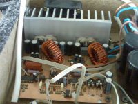
Not quite 6000w, but interesting simple classD topology: IRFB4227, Ir2110, LM319, deadtime with 74HC14, bridge +/-75v, 8 ohm in powered speaker with RCF MB15H401 and Precision Devices PDC2.
It works very well in full range, it is selfoscillating , 400khz at idle, but in this powered speaker i have an active processing, with class AB for highs.
LE. I know that inductors not have optimum position, but it works well, no parasitics.
It works very well in full range, it is selfoscillating , 400khz at idle, but in this powered speaker i have an active processing, with class AB for highs.
LE. I know that inductors not have optimum position, but it works well, no parasitics.
Attachments
Last edited:
hehe, it looks very good, not bad... bridge, so this puts out how much power?
where is the supply, not inside?
where is the supply, not inside?
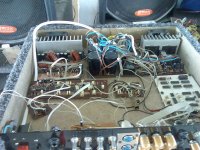
Toroidal trafo is inside of box (not visible); it puts 126 vpeak, means aprox. 1kw@100hz (tested with resistive 8 ohm load).
Deadtime is 47ns, L=13uH, T130-2, configuration ucd like, full bridge with 2 passive pole. And active clamping sensing v-supply, combined with active compressor based on CA3080 (ElectroVoice like). No distorsion at all, even hard forced by turning up full volume (26db like).
Deadtime is 47ns, L=13uH, T130-2, configuration ucd like, full bridge with 2 passive pole. And active clamping sensing v-supply, combined with active compressor based on CA3080 (ElectroVoice like). No distorsion at all, even hard forced by turning up full volume (26db like).
hi
I designed a PCB for this amplifier but I replace transistors with two driver circuits if you have something better please send to me at gabriel_seku@yahoo.com
Wow, that is a nice looking board. Very clean, and logical. Well done! 🙂
Jim
With good PCB layout and gate drive, MOSFET can be used at nearly it's rated Vds, and on the other hand, higher voltage devices have higher capacitances and impose a lot of restrictions on how their body diode can be used. So using parts with higher Vds than required is not a good idea.
Most MOSFET rated at 100V and less will handle body diode hard switching without problem. Some 150V parts are suitable too. With well controlled di/dt, a few 200V/250V ones, and very few 500V/600V ones will handle it too, but charge storage results in high losses on the latter. All higher voltage parts would need external diodes.
IRFB4227 and IRFB4127 are rated at 200V and still can handle hard switching with reasonably low losses. Also, low Rds-on allows to bypass the body diode up to a certain current level (depends on temperature). In my current project, body diodes are only used with 2 ohm load.
Eva, I don't think that all higher voltage parts would need external diodes.
There are 500V/600V MOSFETS available now with very low Qrr/Trr body diodes, the best ones I can find are from Fairchild -- for example:
FDPF16N50UT 500V 16A 0.48ohms trr=65ns qrr=100nC
FDPF10N60ZUT 600V 10A 0.8ohms trr=45ns qrr=52nC
With these (paralleled up) and a fast 500V gate driver you could build a multi-kilowatt half-bridge, which is then bridgeable for truly ludicrous power levels.
Ian
6000watts is too much for a household socket.
You would need at least two supply lines or a 3 phase input.
Only if you want to output continuous sinewaves, which most people would say isn't music ;-)
Fuses and circuit breakers will typically withstand double their rated current for at least 10 seconds.
So even playing the most heavily compressed music with long sustained bass notes, you can safely run a 6kW class-D amplifier from a 3kW socket.
FDPF16N50UT 500V 16A 0.48ohms trr=65ns qrr=100nC
FDPF10N60ZUT 600V 10A 0.8ohms trr=45ns qrr=52nC
With these (paralleled up) and a fast 500V gate driver you could build a multi-kilowatt half-bridge, which is then bridgeable for truly ludicrous power levels.
Ian
to build multi-kilowatt half bridge, it is needed to parallel about 10 of such devices for each rail (20 total), I suppose 🙂
to build multi-kilowatt half bridge, it is needed to parallel about 10 of such devices for each rail (20 total), I suppose 🙂
😀
to build multi-kilowatt half bridge, it is needed to parallel about 10 of such devices for each rail (20 total), I suppose 🙂
Indeed, but they cost less than a dollar each (1000-off), and more parallel devices decreases the package inductance (a single T0220 is ~7nH) for faster switching and less overshoot. It's not difficult getting a lot of TO220s into a small PCB area under a single heatsink, for example using aluminium U-section bars, or just clamping rows of transistors interleaved with rectangular aluminium bars to make a stack which then bolts to a heatsink.
Some hefty gate drivers would be needed, but the Zetex ones are very fast and high current (and cheap!) and reduce the dissipation in the driver chip.
Ian
Last edited:
Indeed, but I expect they're only a couple of dollars each, and more parallel devices decreases the package inductance (a single T0220 is ~7nH) for faster switching and less overshoot. It's not difficult getting a lot of TO220s into a small PCB area under a single heatsink, for example using aluminium U-section bars, or just clamping rows of transistors interleaved with rectangular aluminium bars to make a stack which then bolts to a heatsink.
Some hefty gate drivers would be needed, but the Zetex ones are very fast and high current (and cheap!) and reduce the dissipation in the driver chip.
Ian
High Density Cells could be formed using TO-220[No Row type mounting]and discrete drivers comes in handy to drive them Wild......!!!😉
Yeah, nice looking for classAB fans, but useless for classD.
Ouch! It may not be optimum, but I doubt it is "useless".
- Home
- Amplifiers
- Class D
- 6000W By IRS2092