Hi Chris,
I took this off the old Onsemi data sheet.
MJL0281A (NPN)
MJL0302A (PNP)
These complementary devices are lower power versions of the
popular MJL3281A and MJL1302A
They still available in the bigger case style.
David.
I took this off the old Onsemi data sheet.
MJL0281A (NPN)
MJL0302A (PNP)
These complementary devices are lower power versions of the
popular MJL3281A and MJL1302A
They still available in the bigger case style.
David.
Hi David,
Yes. I figured that out recently as well. Thank you for revisiting this to clarify the numbers. I haven't tried those yet, so I am wondering if the same characteristics as the smaller packaged units had.
Personally, I really liked that smaller case. You don't always need the larger case. The original case was perfect for the Symasym amplifiers, and anything else in the 50 watt range. That and they were perfect for a retrofit into a receiver or amplifier. Once I get less busy, I'll have to buy some and give them a whirl. I'm expecting good things from the larger case styles.
I think the NJL devices are the ones that include the thermal sensing diode.
Hi djk,
Sorry for the silly question, but can you let me know the address of Leach's web site?
BTW, I believe you 100%. In no way am I doubtful of your report. I just would like to see what if any action has been taken against MCM. I always had the idea that MCM seemed to support the TV / VCR service shops. It's that market that has been hit the longest and hardest with fake parts. Reason enough for me to avoid them.
-Chris
Hi Fred,
Excellent news, you can install the diff pair now and either close
the loop around the input board or just give the whole amp a go,
minus the one bad output transistor, and continue to keep the
bias down for now.
I mentioned in one of our conversations that you could leave out
T2 with the larger drivers but then remembered that my amp with
the larger drivers still has T2 so you should probably keep it.
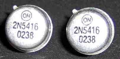
ON never made any with that date code, and these were NPN (they should have been PNP)
http://users.ece.gatech.edu/~mleach/lowtim/
Hi David,
I think the NJL devices are the ones that include the thermal sensing diode.
-Chris
The NJL0281GD/NJL0302GD are the thermatrak bias diode version but you can get these in the NJL0281G/NJL0302G without the thermatrak. These are a 150W TO-264 case.
This is what On Semi says about them,
NJW0281G (NPN)
NJW0302G (PNP)
Preferred Devices
Complementary NPN-PNP
Power Bipolar Transistors
These complementary devices are lower power versions of the
popular NJW3281G and NJW1302G audio output transistors.
So it seems they did just change the packaging from the MJL to NJL.
David.
Hi djk,
Thank you. Now that I see the picture, I seem to remember something about that.
One wonders if these parts would even withstand the voltages if the polarity had been figured out. Probably not.
Thank you very much for the web site. I'll have a read. He's got some interesting stuff on there, like links. There are some really nice looking amps on that page too!
Hi David,
Interesting change of numbers on those parts. I wonder if this means the current parts aren't as tightly matched as the early MJW parts were. If they are the exact same device with those tight tolerances, they are indeed a "preferred device". I feel very strongly that the original parts I got are the best I have ever seen anywhere. I'm still very impressed with them.
On the data sheet, do they still mention that matching outputs can reduce THD (before feedback) by a factor of 10 to 1? This validates what I've known for years.
-Chris
Hi djk,
On the data sheet, do they still mention that matching outputs can reduce THD (before feedback) by a factor of 10 to 1? This validates what I've known for years.
-Chris
I don't see that on the data sheet, but they do say they're all matched to 10%.
They don't always duplicate specs on all their data sheets. I know what you're referring to though. I have seen that on some of their data sheets.
David.
Hi djk,
On the data sheet, do they still mention that matching outputs can reduce THD (before feedback) by a factor of 10 to 1? This validates what I've known for years.
-Chris
•Exceptional Safe Operating Area
•NPN/PNP Gain Matching within 10% from 50 mA to 3 A
•Excellent Gain Linearity
•High BVCEO
•High Frequency
What about matching the drivers as well. Wouldn't that have an effect on distortion in a EF
configuration?
David.
configuration?
David.
Hi Fred,
Excellent news, you can install the diff pair now and either close
the loop around the input board or just give the whole amp a go,
minus the one bad output transistor, and continue to keep the
bias down for now.
I mentioned in one of our conversations that you could leave out
T2 with the larger drivers but then remembered that my amp with
the larger drivers still has T2 so you should probably keep it.
Okay, here's my plan:
I'll use the IT-18 to re-confirm that the original Q1, Q2 and Q9, Q10 are good. If they pass, I will re-install them.
I'll do the same for the original drivers (Q11, Q12).
I'll re-connect T1 and T2.
I'll reconnect one pair of output transistors.
Bring it up slowly, no input, no load. Watch for smoke and current draw. I'll put the scope on the outputs and watch that too.
If it passes that (goes to full voltage without oscillating, reasonable DC offset under 50ma), put the bias back to the factory setting and try again.
If that passes, connect up the remaining working output transistors and try again.
If that passes, put a sinewave in the input and compare it to the output on the scope.
If that passes, test with an 8-ohm load: first no input, then with a sine-wave again. (Can I run an 8-ohm load with only 3 sets of output transistors?)
If that passes, replace the bad output (Q17) and run the test sequence again.
If that passes, run some music into the dang thing!
If that passes, a better than average beer will be required. 😀
Am I missing anything? Is this plan conservative enough?
Last edited:
Sounds good Fred and yes you can run it at 8 Ohm load with 3 set of outputs. Just don't run it to full power for very long. Watch the temperature of the heat sinks. Once you have the last set installed then you can do the bias procedure. Also it's a good idea to keep a close watch on the bias current.
David.
David.
Hi David,
It comes down to making life easy for the differential pair.
Hi Fred,
I think you have a reasonable plan there. You should be able to power an 8 ohm speaker load without too much trouble if you are only missing one output transistor. Watch your bias current. If you search through some of these Adcom threads, you will find a post or two where I explained the bias setting procedure in detail. I have no desire to type it all out again. If you have the entire service manual, that information will be in there.
A beer after the work is always in order, enjoy!
-Chris
Yes, matching the complimentary drivers and back on through the chain will also improve the distortion performance. When On Semi made that measurement, they were simply driving a pair of outputs with a signal generator, no feedback was used. They were proving a point. The better a balance you can achieve throughout the amplifier, the better the distortion performance will be.What about matching the drivers as well. Wouldn't that have an effect on distortion in a EF configuration?
It comes down to making life easy for the differential pair.
Hi Fred,
50 mV? Actually, your DC offset should be below 5 mV once it has settled. I have seen DC offsets reaching 12 VDC as the amp is powered up on some.(goes to full voltage without oscillating, reasonable DC offset under 50ma)
I think you have a reasonable plan there. You should be able to power an 8 ohm speaker load without too much trouble if you are only missing one output transistor. Watch your bias current. If you search through some of these Adcom threads, you will find a post or two where I explained the bias setting procedure in detail. I have no desire to type it all out again. If you have the entire service manual, that information will be in there.
A beer after the work is always in order, enjoy!
-Chris
50 mV? Actually, your DC offset should be below 5 mV once it has settled. I have seen DC offsets reaching 12 VDC as the amp is powered up on some.
I think you have a reasonable plan there. You should be able to power an 8 ohm speaker load without too much trouble if you are only missing one output transistor. Watch your bias current. If you search through some of these Adcom threads, you will find a post or two where I explained the bias setting procedure in detail. I have no desire to type it all out again. If you have the entire service manual, that information will be in there.
A beer after the work is always in order, enjoy!
Thanks Chris, yes, mV is what I meant. Even professional tech writers make typos!
Assuming I get to that point, is it better to run the amp with just the single bad output removed or should I leave one on the other side disconnected to keep things balanced?
I've got the bias procedure spec. I'm looking forward to doing it!
Fred,
Work the bias a bit with one output set in and the 100 ohm current limiters on the fuse holders. Let's make sure you can get to the bias point and say up to 2 or 3 times that value smoothly. Obviously don't leave it turned up high, just watch it on your meter and look for as much as 30 to 40 mV on the emitter resistor.
We don't want the complexity of the full output stage there if there is an issue with bias
control.
It wouldn't hurt to use the new correct drivers if you have confirmed that they are not fakes, on the other hand I can understand the caution in taking small steps.
Hi Fred,
Once you have the amplifier running, please do install the complete compliment of output transistors and recheck your bias levels. That will create an amp that will not bite you down the road, because you will forget that it's one output short in time. Always try to leave equipment in a state were it behaves as any other of the same model would.
Hi Mr. Minix,
I too am impressed that you cared enough to clear the air and leave a post here. This is an extremely positive thing to do in my opinion. May I also suggest that you have an opportunity to really improve your market share.
You are tapped directly into a dedicated group of individuals who buy parts and equipment. DIY, so hands on people here. Many people here also are employed in situations where they use electronic parts in their work, many are also professional people as well.
You aren't expected to deal with every situation that comes up personally, there is a customer service department for that. However, you can get first hand knowledge from the very people who buy from you. Take this situation as an example. I guess you were not made aware that there was a possible issue with improperly marked components, however someone there should have known. At this point you can look into this a bit further in order to enhance your own quality control.
I'd like to also welcome you to this forum. I don't know where your interests lay, but I hope you do get a chance to interact with people here some.
Best regards, Chris
I started a new thread with some more info about my tests on the possible counterfeit 2SC2912s I got from MCM:
http://www.diyaudio.com/forums/parts/165167-counterfeit-2sc2912-others.html#post2155169
Chris (or other mod), it might be useful to move the other counterfeiting posts to that thread.
http://www.diyaudio.com/forums/parts/165167-counterfeit-2sc2912-others.html#post2155169
Chris (or other mod), it might be useful to move the other counterfeiting posts to that thread.
Hi Fred,
Done.
Sorry, not as cleanly as I would have liked. I have asked if another mod can help me move your first post back to the top.
-Chris
Done.
Sorry, not as cleanly as I would have liked. I have asked if another mod can help me move your first post back to the top.
-Chris
Last edited:
Made some good progress this afternoon. The input board is fully repopulated and one pair of output transistors connected. 1 amp fuses installed. Original drivers reinstalled.
With no load, no input, bias at factory setting, I was able to go full voltage with no oscillation! Yay!
DC offset was not great, measuring about 80mvdc after letting the amp warm up for 5 minutes. (Although this is far, far better than the 82vdc it had when it died, so this represents the first time I can say I've actually improved the running condition of the equipment!)
I don't know if I should test further (with a load, input, etc.) or address this offset issue first.
The factory bias setting is about half-way, so there's not enough adjustment to get the off-set down that way. I measured 16.2mv across the emitter resistor with the bias at this setting (16mv is the factory spec).
I did notice that the original drivers have low gain and are poorly matched. (Q11: 106hfe, Q12: 41hfe) but I don't know if that would cause the offset.
Still, I'm feeling optimistic now. Some actual repairing has occurred, and that's a great thing (and one I owe entirely to the amazing generosity of the folk on this board).
Fred,
The unmatched beta of the outputs and drivers is more of an issue with current sharing and output stage distortion. What has the greatest effect on offset is the dif pair in the LTP. The more unbalance the output stage is the greater demand is placed on the input stage to correct offset. If the input stage is unbalance then you will see more offset at the output. Bias is meant to set the the standing current in the outputs not to correct offset.
You might be seeing a mismatch on Q1 and Q2.
David.
The unmatched beta of the outputs and drivers is more of an issue with current sharing and output stage distortion. What has the greatest effect on offset is the dif pair in the LTP. The more unbalance the output stage is the greater demand is placed on the input stage to correct offset. If the input stage is unbalance then you will see more offset at the output. Bias is meant to set the the standing current in the outputs not to correct offset.
You might be seeing a mismatch on Q1 and Q2.
Q1 and Q2 were the original parts, I tested them at 450 and 180hfe, respectively. I swapped out Q2 for a B&D supplied part that tested at 420hfe, so now they should be closely matched (at least as best as my tools can tell).
Now, with 16.0mvdc across the emitter resistor, I'm getting -30 mvdc across the speaker out. I think I'm okay to test with a sine-wave input and then adding a test load.
Do you guys agree?
- Home
- Amplifiers
- Solid State
- Another high DC Adcom GFA-555