Member
Joined 2002
Marfy law for electronic?
Yes, you can double the number of transistors, there will
be almost as much gains as losses , rendering the whole effort useless.
I consider using OP amp and darlingtons for 50w amp...Yes, you can double the number of transistors, there will
be almost as much gains as losses , rendering the whole effort useless.
Attachments

I consider using OP amp and darlingtons for 50w amp...
Not a bad idea at all , provided the op amp has at least
20V/uS slew rate and darlingtons are from Sanken.
Also, the op amp should be high voltage, that will allow
to drive the BJTs on emitter follower mode.
Some people find the NS LM498xx series adequate..
That will be nice, but I like use old available parts.Not a bad idea at all , provided the op amp has at least
20V/uS slew rate and darlingtons are from Sanken.
Also, the op amp should be high voltage, that will allow
to drive the BJTs on emitter follower mode.
Some people find the NS LM498xx series adequate..
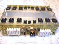
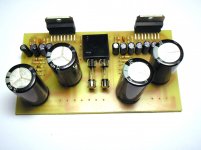
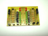
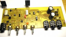
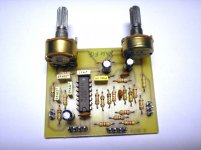
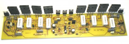
Picture of PCB will be post when amplifier prototype was fuly tested.pics of the pcb ?
Attachments
That will be nice, but I like use old available parts.
How about NJM2068S?
With LM498XX spare only few transistor in VAS, in my circuit (#23) high-performance OP amp can be used, and no limit for high voltage suply.Not a bad idea at all , provided the op amp has at least
20V/uS slew rate and darlingtons are from Sanken.
Also, the op amp should be high voltage, that will allow
to drive the BJTs on emitter follower mode.
Some people find the NS LM498xx series adequate..
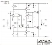
How does this one look? I just simulated it and am gonna try it in a couple of days. The figures are not too bad, so... and got some free time plus some spare FETs at hand. Win-win situation. 😀
Attachments

U try it, and go back with result, I like when people try circuit after simulate best way for learning.😉How does this one look? I just simulated it and am gonna try it in a couple of days. The figures are not too bad, so... and got some free time plus some spare FETs at hand. Win-win situation. 😀
U try it, and go back with result, I like when people try circuit after simulate best way for learning.😉
Just what the truth is.

That's one of the greatest tech jokes! Most people in the whole world do that too!
wahahahah... 😀
wahahahah... 😀
How does this one look? I just simulated it and am gonna try it in a couple of days. The figures are not too bad, so... and got some free time plus some spare FETs at hand. Win-win situation. 😀
If you have no expirience in diy amplifier, then is the best to start with some which will work for sure. I try to inspire you with unusual design to make some experiment, your amplifier look like taken from school book, fill free to use more radical circuit. It's only hobby, don't take amplifiers too serious.
Regards
"Some" doesn't always work even with guys with a load of experience. That's the fun part. Or else every well established circuit would find its place in history and never be tried just because it is "known" to be well working. This is the boring part.If you have no expirience in diy amplifier, then is the best to start with some which will work for sure.
That's a job for guys with electrical/electronic background. I forward the inspiration to them. But thanks anyways.I try to inspire you with unusual design to make some experiment,
Yes it does. It was taken from ESP(sound.westhost.com/project101.htm). ESP pages are really very informative and academic, like a school of info. But the resistor values were not shown there in the page. The values are chosen by myself by trial and error method to have as good performance in the simulator as possible. This doesn't make me a circuit designer. I do all this for fun and fun only. For example, if the circuit oscillates after I make it, it will be a ton more fun. I'll get more to talk about.your amplifier look like taken from school book,
It solely depends on my mood. I feel free to try bogus circuitry just to see what mess it does. For example I made a Death of Zen power amp some months ago, just do discover that it sounds so awfully bad. But again, it's only me.fill free to use more radical circuit.
Everybody knows this is a hobby and that said nobody should take this too seriously. I didn't. See I posted an amp that works in such a well known "established" way that it makes you feel like it is from school book. However, I get really serious when I am soldering the parts on the board. Or else things could go wrong. I have a habit of having the circuit at hand work in the first try. But I can't be too sure for the next time; it might go BANG; so often amps demands "too" serious attention even if it's from school book.It's only hobby, don't take amplifiers too serious.
Regards
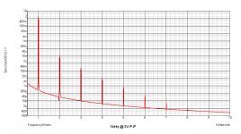
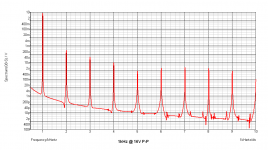
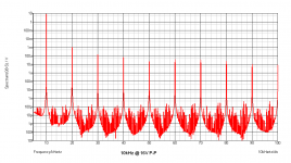
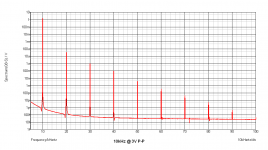
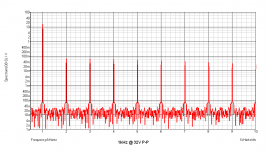
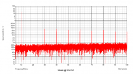
I suggest you simulate every circuit you post and show the results of simulation from the very first post, a simple thing expected from someone who posts "more radical" circuits. Trust me, simulation does help and often saves days of pain, for others. That little bit of seriousness will save a lot of headache for the "not too serious" DIYers. Graphs speak louder than words.
cheers.
Last edited:
I don't want to criticise you, just wondering why "sony" schematics don't inspire you? I share only well tested circuit. This one is only experimental, but will be funktional in future.
Regards
Regards
Attachments
- Home
- Amplifiers
- Solid State
- 50W mosfet amplifier IRF540/IRF9540