Thank you, but I see much diferent design.
There s only the Vas that is different...
Actually, everything is different exept full simetry and using IRFPs.There s only the Vas that is different...
Last edited:
You can use mine as a shortcut to get started, if you wish.
Don't take my doubts about needing a cascode to mean you
should have to start the translation over again from scratch.
Thanks. Where is your LTspice file ?
http://www.diyaudio.com/forums/soli...mplifier-irfp240-irfp9240-11.html#post2112147
Post# 108, but needs changes as described in #109 and #110 before it (the sim) works.
Post# 108, but needs changes as described in #109 and #110 before it (the sim) works.


Thanks, 100nF of Zobel network must be conected on P GND, no IN GND. P GND and IN GND can not be conected together, see post #145 and original PCB.Hi all,
since IRFP9240 was hard to find here, I used IRF640/9640 (TO-220) with change in PCB design.
Hope it will be helpful to others.
Regards Mile
Last edited:
[url]http://www.federmann.cz/images/stories/Nf/HQQF/505/GQQF-55-505.gif[/url] [/ IMG]
[B]Has simplified and more reliable version.[/B]
[B]Has simplified and more reliable version.[/B]
[URL]http://www.federmann.cz/images/stories/Nf/HQQF/505/GQQF-55-505.gif[/URL] [/ IMG]
[B]Has simplified and more reliable version.[/B][/QUOTE]
Reliable :confused:
[URL]http://www.diyaudio.com/forums/solid-state/162081-dc-servo-mosfet-amplifier-2.html[/URL]
Regards
Last edited:
I emitter resistors of several larger, take up less space and have a smaller inductance.
Each HEXFET Power MOSFET has a capacitor 1mF/100V (2.2 mF/63V) and 100n/100V
Each HEXFET Power MOSFET has a capacitor 1mF/100V (2.2 mF/63V) and 100n/100V
Last edited:
That'll never work... You didn't even round the corners.
Just look! 90deg angles everywhere. Then linking it all to
a time release GIF capsule only makes the matter worse.
Think of the phase shift???
Just look! 90deg angles everywhere. Then linking it all to
a time release GIF capsule only makes the matter worse.
Think of the phase shift???
See? Round corners = much better-er-est!
And something to be said for a Black'N'White drawing too. How your
schematic gonna work with all those funky colors what take 5min just
to draw the whole GIF (Federmann post#149)?
Seriously though, why you guys drive so many parallel output devices?
The Apex pushes enough Watts, I'd agree at least two, but four???
This seems a very conservative design decision. I thought even these
old MOSFET types offered far better SOA?
I guess you can always DNI a needless MOSFET later.
Pretty hard to add holes and traces after the fact...
Am I killing myself here, with only one MOSFET per 55V rail?
Mine are in big TO3 cans. My P-CH has a funny JAN number,
2N6804 but is the same like 9240. Current limiters kick at 7A.
Attachments
Last edited:
Seriously though, why you guys drive so many parallel output devices?
The Apex pushes enough Watts, I'd agree at least two, but four???
May be 1 to 8 pairs, power 125W ... 1000W. For 4 pairs of 500W.
I don't see a problem with any of these topology,
except some need high voltage rail to drive gates.
I turned mine inside out, but don't quite reach the
full rails either, probably cause I didn't parallel...
I'm a little dissapointed your drawing reveals no
component details to make a fair comparison vs
Apex? If you are going to claim better than him,
or me, show your stuff!
I'll even cut you some slack if you forget to round
some of the corners... Your English is fine, I'm the
idiot here. Won't write my own language properly.
Last edited:
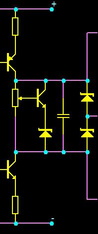
I like your design, I have amplifier with one BJT per 55V rail.See? Round corners = much better-er-est!
And something to be said for a Black'N'White drawing too. How your
schematic gonna work with all those funky colors what take 5min just
to draw the whole GIF (Federmann post#149)?
Seriously though, why you guys drive so many parallel output devices?
The Apex pushes enough Watts, I'd agree at least two, but four???
This seems a very conservative design decision. I thought even these
old MOSFET types offered far better SOA?
I guess you can always DNI a needless MOSFET later.
Pretty hard to add holes and traces after the fact...
Am I killing myself here, with only one MOSFET per 55V rail?
Mine are in big TO3 cans. My P-CH has a funny JAN number,
2N6804 but is the same like 9240. Current limiters kick at 7A.
http://www.diyaudio.com/forums/solid-state/164093-100w-ultimate-fidelity-amplifier-3.html
Regards
Thanks, 100nF of Zobel network must be conected on P GND, no IN GND. P GND and IN GND can not be conected together, see post #145 and original PCB.
Regards Mile
Thanks for the corrections.
- Home
- Amplifiers
- Solid State
- MOSFET Amplifier IRFP240/IRFP9240