I suppose if one is locked into the idea there can only be one plus and one minus supply this is a good design- now if you leave that idea behind then... a lot of improvement can be made and a lot of those slow current sources can be replaced by fast resistors. Every current source slows the propagation through the amp.
OK, tell me what makes a resistor "faster", if the speed is limited by how fast it takes to charge a capacitor through it? The overall change in voltage will happen faster with the current source. It may be faster initially with the resistor, but it slows dowwwwwn as the cap approaches full charge. There is no free lunch. In either case, the amp will be in slew limit and distorting. And if we're talking about small-signal response, there is no differnece in speed as it intentionally dominated by a pole somewhere.


Pozdrav!
Posto veoma SLABO se izrazavam na engleski hocu nesto da pitam na Srpski😛itanje-Jel mozes da okacis ovde na ovom sajtu PCB za ovaj pojacavac i nekoliko reci o njegovom zvuku??!
Unapred hvala!
Posto veoma SLABO se izrazavam na engleski hocu nesto da pitam na Srpski😛itanje-Jel mozes da okacis ovde na ovom sajtu PCB za ovaj pojacavac i nekoliko reci o njegovom zvuku??!
Unapred hvala!
Pozdrav!
Posto veoma SLABO se izrazavam na engleski hocu nesto da pitam na Srpski😛itanje-Jel mozes da okacis ovde na ovom sajtu PCB za ovaj pojacavac i nekoliko reci o njegovom zvuku??!
Unapred hvala!
Ni moj engleski nije bolji, ali zabranjeno je koriscenje drugih jezika na forumu, posalji PP ili email.
Pozdrav Mile
Aha! A better question might be "What's wrong with current sources?".OK, tell me what makes a resistor "faster"...
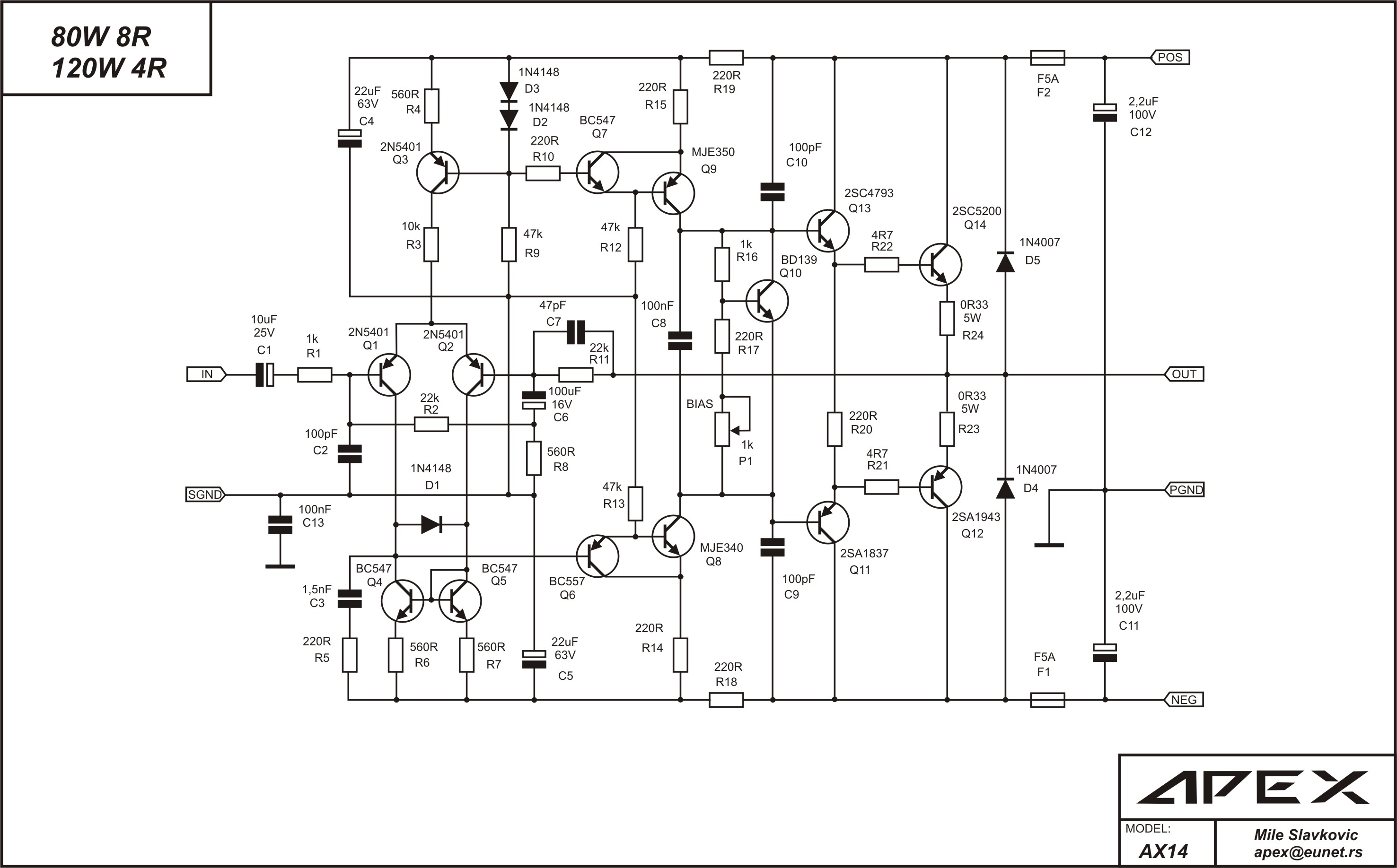
With a simple current source like Q3 in this circuit, the collector-base capacitance is effectively in parallel with the current source, so it's dynamic impedance will reduce at high frequencies.
Perhaps this is why Mile put a 10K resistor in series with it - to keep the impedance high at high frequencies.
Also - The transistor's Hfe, Vbe and Ccb all vary non-linearly with collector voltage, so the current will vary with voltage and will be distorted.
Replacing the entire current source with e.g. a 220K resistor connected to a well regulated +300V supply would eliminate the distortion and high-frequency problems.
For the input stage, these aren't serious problems though, because there is very little voltage swing on the current source and the LTP has good rejection anyway.
The second stage is much more important, but here a Baxandall super-pair has been used for the current source (and the VAS) to eliminate all the base-current distortions.
btw: Neither of the current sources in this circuit will hurt propagation delay, with or without a bit of capacitance.
-----------------------------------------------
Sorry for the hijack, Mile.
This looks like a really nice circuit. What rail voltage or power is it intended for?
Cheers - Godfrey
Circuit was tested on +/-90V rail voltage, but with single pair 2SC5200/2SA1943 +/-56V is maximum. 80W on 8R load with low THD.
Regards
Regards
OK, tell me what makes a resistor "faster", if the speed is limited by how fast it takes to charge a capacitor through it? The overall change in voltage will happen faster with the current source. It may be faster initially with the resistor, but it slows dowwwwwn as the cap approaches full charge. There is no free lunch. In either case, the amp will be in slew limit and distorting. And if we're talking about small-signal response, there is no differnece in speed as it intentionally dominated by a pole somewhere.
Sure easy.
First off the current source has its own capacitance in parallel with the gain stage assuring slower response than a resistor. Second if the output transistor supply voltage is say ±50 then the last gain stage can run on -50 (or -75 regulated) and +150 or higher using a very simple voltage doubler and tripler. That resistor then has 150 volts drop to ground and not 50. This also does not increase the voltage requirement of the transistor as when the last gain stage transistor is off the voltage cannot exceed the positive rail voltage plus a few diode drops--- somewhere very near that 50 volts. This also make the amp much more efficient as drive transistor may be driven into saturation. So instead of 120 watts 140 or more may be available.
All amps have slew limiting and so long as slew limiting is out of the audio band there should be no signal to invoke such limit so no slew induced distortion occurs. Slew limit is not related to small signal bandwidth anyway as shown by hundreds of op-amps. Slew limit is only related to large (full power) bandwidth and for audio that is usually defined as 20kHz.
What does this mean? For small signal the resistor biased at the same current will always be faster than a current source at the same current because of the reduced capacitance on the collector to ground. Much higher voltage on the plus supply deals with the bias variation nicely.
Not my idea by the way. Read it in AES journal article by Tomlindsman Hollman I think and several others.
See, very easy once explained.
Last edited:
hi every body i very new new 2 this field i corrected the circuit as said by wahab and introduced a cap parallel to R20 as I read in G.randy slones book it help in faster turn on and turn off of the transistor if I am correct plz specify the value of the cap and may be the value of R20 needs to be lowered...........
modified circuit
regards
sekhar
modified circuit
An externally hosted image should be here but it was not working when we last tested it.
regards
sekhar
Circuit was tested on +/-90V rail voltage, but with single pair 2SC5200/2SA1943 +/-56V is maximum. 80W on 8R load with low THD.
Regards
Do a little research on SOAR. I think you may find those voltages are too high. 😱
+/-56V is maximum for 8R load with single pair 2SC5200/2SA1943.Do a little research on SOAR. I think you may find those voltages are too high. 😱
Do not change anything on your own before you made functional amp, then you try with upgrades.hi every body i very new new 2 this field i corrected the circuit as said by wahab and introduced a cap parallel to R20 as I read in G.randy slones book it help in faster turn on and turn off of the transistor if I am correct plz specify the value of the cap and may be the value of R20 needs to be lowered...........
modified circuit
regards
sekhar
Regards
What I really like about this amp is usage of Baxandall Super-pair transistors for VAS transistors...ultra fast, ultra high output impedance, ultra low output capacitance...nice!
Nice but what about the PCB? Most diyers like me have no skills on making their own PCB layout. That is the biggest problem in making an amplifier.
Go to post #18, and in my thread "150W mosfet amplifier with IRFP250" in post #31, #34 U can find PCB for Kelvin amp. In my thread "DC servo mosfet amplifier" U can find PCB for PSU and Protect, can be use with any amp module.Nice but what about the PCB? Most diyers like me have no skills on making their own PCB layout. That is the biggest problem in making an amplifier.
Regards
Last edited:
I am looking forward on building this amp looks very good as i have corrected the schematics according to wahab any more inputs will be very helpful and the pcb layout
plz
regards
sekhar
plz
regards
sekhar
Do not change anything on your own before you made functional amp, then you try with upgrades.
Regards
i just corrected the resistor values as suggested by wahab and added a cap across R20 to decrease turn off time ......... as read by me in Slones book......
neways will make my own pcb and post it ........... it would be better if u could post working pcbs pics
regards
sekhar
U can saw correct schematics in post #22. this is very new amplifier, I suggest to build Kelvin amp, it is similar and be used over a year ago.i just corrected the resistor values as suggested by wahab and added a cap across R20 to decrease turn off time ......... as read by me in Slones book......
neways will make my own pcb and post it ........... it would be better if u could post working pcbs pics
regards
sekhar
Regards
r u suggesting this amp and do have any pcb for this and how r the sonics..................
how can a VI limiter be introduced in circuit to prevent o/p stage destruction in event of short circuit
circuit
regards
sekhar
how can a VI limiter be introduced in circuit to prevent o/p stage destruction in event of short circuit
circuit
regards
sekhar
r u suggesting this amp and do have any pcb for this and how r the sonics..................
how can a VI limiter be introduced in circuit to prevent o/p stage destruction in event of short circuit
Read post #34.
Regards
What I really like about this amp is usage of Baxandall Super-pair transistors for VAS transistors...ultra fast, ultra high output impedance, ultra low output capacitance...nice!
And most probably ultra unstable too, Ive dug around, this design by apex is a clone of a yamaha amp, only that yamaha used it as a subwoofer amp, thats why you see compensation done like that 330pf cap across the feedback resistor, there was no intention for this amp to operate to normal frequencies required for full range amp. From what I can read about the yamaha amp is that it was discontinued prematurely because of problems, I can guess what those were......
Do some sims, and youll find it impossible to stabilise no matter how you try to compensate it.
- Home
- Amplifiers
- Solid State
- 100W Ultimate Fidelity Amplifier