Just saying these diodes rarely if ever short out in this application (if not externally abused)
V R14 is a diode drop, same in both channels showing both D5 and D6 to be OK
Not sure about V R16 need to recheck that voltage since Q4 has been replaced.
Check thermal switch T1 for bad (intermittent) contacts is more likely in my experience than D5 and D6.
Edit> I doubt if we will ever rationalize why Q7 BE failed.
Last edited:
OK, so something is not right. I don't think you'll do any more damage if you bring up the voltage to where it draws say .1 to .2 amp on the variac. Then measure the emitter resistor voltages. This will tell us if one or more output devices is bad. If the issue is balanced across the outputs then it is probably the drivers or bias circuit. You could just replace the drivers at this point if you want to avoid risking the outputs.
Latest progress:
Tested all emitter resistors (R24-31) out of circuit. They all pass at .8ohm.
I pulled and tested Q11 and Q12 with following results:
no leakage (according to IT-18)
pass the diode test (I can post those readings if they're useful)
Q11 81hfe
Q12 14hfe
I replaced them with a poorly matched set of 30/31 with higher gain (Q11:217hfe, Q12: 129hfe).
I replaced C8 because it looked tatty and old.
Tested the thermistor, T2, it slowly increased in resistance until stabilizing at 1.488kohm.
I then reassembled everything and with Q1 and Q2 still pulled, ran the power up to 68vdc on the rails, with no problems or excess current draw, just like before the drivers were replaced.
I then set up the previous test, with Q1 and Q2 still pulled and Q7-C connected to the (+) rail.
I ran the power up and still had the same issue as before, pulling excessive current at about 50vdc. *sigh*
I then set about testing voltages in the output boards. I ran up the power to 33.5vdc on the rails, which gave me +28.0vdc at the outputs. (This was pulling about .1 amp at 53vac).
With the power set at this level, I tested voltage across the emitter resistors with the following results:
R24: 18.3mvdc
R25: 11.0
R26: 10.9
R27: 10.8
R28: -13.5mvdc
R29: -12.3
R30: -13.0
R31: -12.6
I also tested voltages across the drivers EBC:
Q11
B-E: 0.585vdc
B-C: 60.1vdc
C-E: 60.8vdc
Q12
B-E: 0.600vdc
B-C: 4.35vdc
C-E: 4.98vdc
Not really the conclusive driver failure we were hoping for. But I'm suspicious of R24. What do you guys think?
Last edited:
Just saying these diodes rarely if ever short out in this application (if not externally abused)
V R14 is a diode drop, same in both channels showing both D5 and D6 to be OK
Not sure about V R16 need to recheck that voltage since Q4 has been replaced.
Check thermal switch T1 for bad (intermittent) contacts is more likely in my experience than D5 and D6.
I could just jumper T1 while I'm testing and trouble-shooting the amp, right? I could try pulling it and testing continuity while I heat it with a hair dryer. Or is there a more scientific test?
I have some new diodes now, so maybe I'll just swap out Wahab's diodes to eliminate that variable.
Last edited:
Latest progress:
Tested all emitter resistors (R24-31) out of circuit. They all pass at .8ohm.
I pulled and tested Q11 and Q12 with following results:
no leakage (according to IT-18)
pass the diode test (I can post those readings if they're useful)
Q11 81hfe
Q12 14hfe
I replaced them with a poorly matched set of 30/31 with higher gain (Q11:217hfe, Q12: 129hfe).
I replaced C8 because it looked tatty and old.
Tested the thermistor, T2, it slowly increased in resistance until stabilizing at 1.488kohm.
I then reassembled everything and with Q1 and Q2 still pulled, ran the power up to 68vdc on the rails, with no problems or excess current draw, just like before the drivers were replaced.
I then set up the previous test, with Q1 and Q2 still pulled and Q7-C connected to the (+) rail.
I ran the power up and still had the same issue as before, pulling excessive current at about 50vdc. *sigh*
I then set about testing voltages in the output boards. I ran up the power to 33.5vdc on the rails, which gave me +28.0vdc at the outputs. (This was pulling about .1 amp at 53vac).
With the power set at this level, I tested voltage across the emitter resistors with the following results:
R24: 18.3mvdc
R25: 11.0
R26: 10.9
R27: 10.8
R28: -13.5mvdc
R29: -12.3
R30: -13.0
R31: -12.6
I also tested voltages across the drivers EBC:
Q11
B-E: 0.585vdc
B-C: 60.1vdc
C-E: 60.8vdc
Q12
B-E: 0.600vdc
B-C: 4.35vdc
C-E: 4.98vdc
Not really the conclusive driver failure we were hoping for. But I'm suspicious of R24. What do you guys think?
You pulled all the emitter resistors? That would have been a good time to test the outputs one at a time. Let me ask were you planning to remove the outputs to redo the thermal grease? This is odd, I expected to see higher current on one of the negative output transistors not a positive one, yet we are seeing increased current as indicated by R24 in Q17. So there is no conclusive measurement here. What you are seeing there mainly is the idle bias current because the 4ma through the bias network is turning the bias on. Now, you're going to have to reset the bias so a simple way to take the bias current out of the equation is to turn P1 to the minimum resistance position, this should turn off all of the outputs on the negative side.
Please try this and report the voltages on the resistors and see if the high current is still there. I want to rule out any problem in the bias network. By the way, have you tested R21, it is stressed under short circuit conditions.
I would really be surprised if one of D2 or D3 has reduced breakdown but you can remove them for this test, they are only needed when driving an inductive load. And there is not enough current in the output stage to explain the draw from the line.
If the problem is still there after all of this, I would remove Q4 to further rule out the idle current, leave it out.
If still bad remove power transistor Q17 that increased voltage is highly suspicious. All you need is one power transistor on each side so you could continue to remove them until the problem goes away.
A few things to consider, if you have it apart while working on it be careful that no screws or anything that you change is involved in making or completing an electrical circuit.
Has the possibility of an output transistor short to the heatsink been considered?
Instead of removing Q4> Dont forget you can remove the bias by opening T1 by removing one wire.
Can't the TO-3 Power transistors can be taken out of circuit by lifting one leg of an emmiter resistor and taking off the screws.
Can't the TO-3 Power transistors can be taken out of circuit by lifting one leg of an emmiter resistor and taking off the screws.
Instead of removing Q4> Dont forget you can remove the bias by opening T1 by removing one wire.
Can't the TO-3 Power transistors can be taken out of circuit by lifting one leg of an emmiter resistor and taking off the screws.
I'm leaning more toward the output stage but I thought it would be good to rule out T4, that it might be breaking down. Opening T1 would work if we believe that Q4 is good. That should work with the outputs also. I don't recall if they are socketed.
I'm leaning more toward the output stage but I thought it would be good to rule out T4, that it might be breaking down. Opening T1 would work if we believe that Q4 is good. That should work with the outputs also. I don't recall if they are socketed.
Q4 is new and was tested before installation. I can diode test it again, in circuit, but it seems better not to heat it again to remove it. The outputs are not socketed. At this point, once the fault is found and the amp is running again, I'll replace all the power semis. So I suppose I could just bite the bullet and rebuild the output sections and be done with it. But obviously I don't want to do that until the fault is diagnosed.
I understand what you're saying about rebuilding the output stage, but keep in mind we just want to make sure that it isn't something like a solder bridge.
Please note the position of the bias pot, write it down, then turn it so that there is no bias. You could just tack a wire across the pot as I am a bit suspect of the pot. Test and tell us the emitter resistor voltages.
Next I would remove Q17 this is highly suspect.
If that doesn't do it, it would help to push the current a little more, say .2 on the Variac. What we are seeing doesn't make any sense, the only path for high current is through the output stage, and we are not seeing much more than the bias current so it is not possible to diagnose.
Also when you read EBC voltages please read them with respect to ground.
Hi Fred,
Your emitter drops look reasonable. Sanity check: add up all the ones on the PNP side, do the same for the NPN side and compare them. That's what I just did quickly in my head.
Keep in mind that an open emitter resistor often has a reasonable amount of voltage across it. That is an easy thing to miss, sending you down the wrong path.
Is it possible that the bias control may be turned up too high? Have you checked the bias control for damage? It may be open at the wiper or one end. Your DC offset still bothers me as well. Have you checked the little ground resistor that likes to open? Measure the resistance between the two RCA jacks on the back and let us know what you get. If all that looks good, measure from each transistor base to ground on the input diff pair. They should be equal by a few mV at the most (if they are matched).
Hi wahab,
You sure get a bee in your bonnet! If one diode was shorted, excessive bias current would not occur. However, it's easy enough for Fred to measure the voltage drop while the amp has some power. As stated by others here, the thermal switch fails far more often than these diodes. I have never once had to replace them - ever. I've serviced tons of these amplifiers.
Hi Pete,
When measuring the voltages in an output stage, it's far more useful to use the speaker output as the reference for your meter. Then everything tends to make more sense when you are measuring.
-Chris
I'm at work right now (though obviously not working🙂), and have a couple of questions before tonight's round of testing.
I checked all the emitter resistors by lifting one leg and checking resistance. They all read .8 ohm. Is there another check I should be doing?
The bias control is set to where it was originally (I marked it with a sharpie). I was thinking of replacing it with a sealed, multi-turn pot. Since you and Pete both identify it as a possible concern, I could replace it now, or just pull and jumper it. I did clean it and rotate it multiple times, and I could see it smoothly increase and decrease voltage on the scope, but I haven't tested it any further.
Which one is the "little ground resistor"?
When you say measure the resistance between the two RCA jacks, do you mean the resistance between the + and - of each jack, or something else? A little confused there...
Also, you are saying I should measure the voltage at the base of Q11 and Q12 using the ground (as opposed to, say, base to collector)? They are not particularly well matched since all I have is DVM for testing. The currently installed pair differ by about 100hfe.
Can you guys tell me literally, exactly how you would measure output stage and/or EBC voltages? You can "pretend" you're talking to an idiot and tell me literally where to put the probe leads.
When I measured the drivers above, I just put, for example, one lead on the C and the other on E to measure voltage. Are you saying I should put the negative probe on common ground? I suppose that does make more sense.
Yep, 300 posts later, still a noob. 😱
Keep in mind that an open emitter resistor often has a reasonable amount of voltage across it. That is an easy thing to miss, sending you down the wrong path.
I checked all the emitter resistors by lifting one leg and checking resistance. They all read .8 ohm. Is there another check I should be doing?
Is it possible that the bias control may be turned up too high? Have you checked the bias control for damage? It may be open at the wiper or one end.
The bias control is set to where it was originally (I marked it with a sharpie). I was thinking of replacing it with a sealed, multi-turn pot. Since you and Pete both identify it as a possible concern, I could replace it now, or just pull and jumper it. I did clean it and rotate it multiple times, and I could see it smoothly increase and decrease voltage on the scope, but I haven't tested it any further.
Your DC offset still bothers me as well. Have you checked the little ground resistor that likes to open? Measure the resistance between the two RCA jacks on the back and let us know what you get. If all that looks good, measure from each transistor base to ground on the input diff pair. They should be equal by a few mV at the most (if they are matched).
Which one is the "little ground resistor"?
When you say measure the resistance between the two RCA jacks, do you mean the resistance between the + and - of each jack, or something else? A little confused there...
Also, you are saying I should measure the voltage at the base of Q11 and Q12 using the ground (as opposed to, say, base to collector)? They are not particularly well matched since all I have is DVM for testing. The currently installed pair differ by about 100hfe.
When measuring the voltages in an output stage, it's far more useful to use the speaker output as the reference for your meter. Then everything tends to make more sense when you are measuring.
Can you guys tell me literally, exactly how you would measure output stage and/or EBC voltages? You can "pretend" you're talking to an idiot and tell me literally where to put the probe leads.
When I measured the drivers above, I just put, for example, one lead on the C and the other on E to measure voltage. Are you saying I should put the negative probe on common ground? I suppose that does make more sense.
Yep, 300 posts later, still a noob. 😱
Yes, black DVM lead to ground is what I prefer, for most of the semis but I could go along with Chris suggesting black to speaker output for the output transistors.
Yes, black DVM lead to ground is what I prefer, for most of the semis but I could go along with Chris suggesting black to speaker output for the output transistors.
But when I measure the voltage across the emitter resistors I just put the leads literally on either side of the resistor, right?
Sorry to clog the thread with these basics, but I don't like to leave assumptions unexamined when working remotely!
Heck youve replaced almost all transistors by now...
how about measuring the betas of the TO-3s on each rail?
Start by pulling the collector screws & one common lead of R24 you dont have to desolder the EB pins, right?
how about measuring the betas of the TO-3s on each rail?
Start by pulling the collector screws & one common lead of R24 you dont have to desolder the EB pins, right?
Heck youve replaced almost all transistors by now...
QUOTE]
isn t it?...
But when I measure the voltage across the emitter resistors I just put the leads literally on either side of the resistor, right?
Sorry to clog the thread with these basics, but I don't like to leave assumptions unexamined when working remotely!
Yes, because the voltage is so small, go right across. The resistor is acting like what we call a current shunt and you want the voltage across it.
Infinia, is right about removing the TO3 screws, they will isolate the collectors, then if you isolate the emitter by the resistor, that is essentially out of circuit.
Do Q17 first.
Nothing wrong with replacing all the low cost semis, and the drivers are an upgrade, so you're doing an excellent job!
You even tested beta and several were low.
Last edited:
Okay, today's tests.
Same state as previous tests: Q1 and Q2 removed, Q7-C to + rail.
Turned the bias pot all the way down. Slowly turned up the power. As I approach 40vdc on the rails, the output starts to "pulse" with a very slow oscillation. The scope trace at the output shows a jagged, square-wave-ish, voltage drop about every 40ms. I swear it's in 4/4 time.🙂
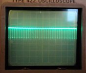
When I re-set the bias back up to the factory setting, you can still see this oscillation on the scope (I tried to get a pic below), it's just higher frequency. The frequency of the oscillation also increases as power increases. The attached pic is at 37.5v on the rails, 2ms/div, 1v/div. Obviously, current draw increases with the oscillation.
I continuity tested both drivers and all the output transistors for case-to-heatsink shorts. I did not find any.
I tested resistance from the ground sleeve of the input jack to the common ground, it was 00.1 ohm in each channel.
I took Q17, Q18 and Q19 out of circuit by removing the screws and lifting a leg of the resistor, bringing the amp up to the oscillation point (34+ vdc on the rail), after removing each transistor. it oscillated.
That's all I had time for today. I'll get to the last five transistors tomorrow, hopefully. I'll leakage and gain test them while they're out of circuit, but I've got a fishy feeling they'll test okay. *sigh*
Same state as previous tests: Q1 and Q2 removed, Q7-C to + rail.
Turned the bias pot all the way down. Slowly turned up the power. As I approach 40vdc on the rails, the output starts to "pulse" with a very slow oscillation. The scope trace at the output shows a jagged, square-wave-ish, voltage drop about every 40ms. I swear it's in 4/4 time.🙂
When I re-set the bias back up to the factory setting, you can still see this oscillation on the scope (I tried to get a pic below), it's just higher frequency. The frequency of the oscillation also increases as power increases. The attached pic is at 37.5v on the rails, 2ms/div, 1v/div. Obviously, current draw increases with the oscillation.
I continuity tested both drivers and all the output transistors for case-to-heatsink shorts. I did not find any.
I tested resistance from the ground sleeve of the input jack to the common ground, it was 00.1 ohm in each channel.
I took Q17, Q18 and Q19 out of circuit by removing the screws and lifting a leg of the resistor, bringing the amp up to the oscillation point (34+ vdc on the rail), after removing each transistor. it oscillated.
That's all I had time for today. I'll get to the last five transistors tomorrow, hopefully. I'll leakage and gain test them while they're out of circuit, but I've got a fishy feeling they'll test okay. *sigh*
Attachments
Okay, today's tests.
Same state as previous tests: Q1 and Q2 removed, Q7-C to + rail.
Turned the bias pot all the way down. Slowly turned up the power. As I approach 40vdc on the rails, the output starts to "pulse" with a very slow oscillation. The scope trace at the output shows a jagged, square-wave-ish, voltage drop about every 40ms. I swear it's in 4/4 time.🙂
When I re-set the bias back up to the factory setting, you can still see this oscillation on the scope (I tried to get a pic below), it's just higher frequency. The frequency of the oscillation also increases as power increases. The attached pic is at 37.5v on the rails, 2ms/div, 1v/div. Obviously, current draw increases with the oscillation.
I continuity tested both drivers and all the output transistors for case-to-heatsink shorts. I did not find any.
I tested resistance from the ground sleeve of the input jack to the common ground, it was 00.1 ohm in each channel.
I took Q17, Q18 and Q19 out of circuit by removing the screws and lifting a leg of the resistor, bringing the amp up to the oscillation point (34+ vdc on the rail), after removing each transistor. it oscillated.
That's all I had time for today. I'll get to the last five transistors tomorrow, hopefully. I'll leakage and gain test them while they're out of circuit, but I've got a fishy feeling they'll test okay. *sigh*
We need to stop the oscillation, which I have a feeling has something to do with Q4 - not that it makes any sense. If you've got oscillation we need to stop it before you pull the outputs. It is clear that it works fairly well below 40V so normal low voltage testing of the parts is not going to tell you much. We are simply trying to use the full voltage of the power supply to swing the output rail to rail and find any leaking devices. But first we have to stop the oscillation, then we have to see imbalance in the emitter resistor voltages or whatever might indicate what the real problem is.
Opening T1 will at least turn off Q4, that might be the simplest way to go.
I don't know, perhaps you're going to shotgun the output stage now, what if it is D1 or D2 and you replace all the outputs? Removing them (D1 and D2), and them not being the problem is not foolish, it rules them out. The output stage saw some huge currents, enough to blow the fuse, those diodes are there to absorb inductive back voltage. What if you replace all the outputs, and it still does it because it was D1 or D2?
If you recall, I said from the start that this would be testing the VAS and the current source for breakdown as well as the output stage. I would have had you remove the VAS and current source, but you skipped that saying you replaced them. Well there is another good reason, we are not completely isolated from them as it is now, perhaps you built an oscillator.
Last edited:
Rethinking this:
Please jump below and do the Power Supply test first.
I had expected us to have found the problem by now, and when I remove devices to test I usually like to leave them out and do as much isolated testing as possible. I don't know how easy it is to disconnect the drivers, but considering that they are not the right ones you might be fine doing it again. If you remove the drivers, you can do essentially a leakage/breakdown test on the output stage. I strongly suggest that you do this. Leave any disconnected outputs disconnected and reconnect them one at a time only if it passes:
Remove the drivers.
jumper across R21 to force the output stage into class B with zero idle current. Now jumper a 1K E-C on Q12 for the pos test, and E-C on Q11 for the neg test, when the 1K is on one side the other should be open. With D1 and D2 removed you are now only testing the output devices.
You can obviously do resistance and IT-18 tests on any outputs that you already have isolated.
Do not jump to the next step if it passes, let's think about it first.
I think this is the best way to proceed, it can't get much simpler. Get the output right, then put in the drivers, and build it back up to the full amp.
We are spending a lot of time on this, if your plan is to replace all of the outputs, but I agree that it is best to fully understand the problem.
POWER SUPPLY TEST:
The bridge rectifier could be bad on the non-working channel.
You could remove the fuses for this channel to confirm that the other channel is working, it would also be good to know the line current at a few Variac settings.
Confirm the supply voltage, and take a look with the scope referenced to ground to look for ripple, use AC coupling on the scope.
Really it is probably best to do this first, again simplify as much as possible.
Last edited:
We need to stop the oscillation, which I have a feeling has something to do with Q4 - not that it makes any sense. If you've got oscillation we need to stop it before you pull the outputs. It is clear that it works fairly well below 40V so normal low voltage testing of the parts is not going to tell you much. We are simply trying to use the full voltage of the power supply to swing the output rail to rail and find any leaking devices. But first we have to stop the oscillation, then we have to see imbalance in the emitter resistor voltages or whatever might indicate what the real problem is.
Opening T1 will at least turn off Q4, that might be the simplest way to go.
I don't know, perhaps you're going to shotgun the output stage now, what if it is D1 or D2 and you replace all the outputs? Removing them (D1 and D2), and them not being the problem is not foolish, it rules them out. The output stage saw some huge currents, enough to blow the fuse, those diodes are there to absorb inductive back voltage. What if you replace all the outputs, and it still does it because it was D1 or D2?
If you recall, I said from the start that this would be testing the VAS and the current source for breakdown as well as the output stage. I would have had you remove the VAS and current source, but you skipped that saying you replaced them. Well there is another good reason, we are not completely isolated from them as it is now, perhaps you built an oscillator.
I see what you're saying in your "re-thinking" post, but this post did get me thinking. At first I thought the oscillation was a pre-existing condition that caused the failure of Q7. However, on further thought it seems to me unlikely that the oscillation was present in the initial fault condition. Wouldn't it have smoked and burned more parts (e.g. R21)? If, and only if, that assumption is correct, then the only explanation for the oscillation is that I introduced somehow (I "built an oscillator" as you said).
Looking back, the oscillation was present after I did the following:
Replaced: Q4, Q7, Q8, R7, R8
Removed and reinstalled: Q11
So what do you think of an approach that first takes these components either out of circuit or verifies their correct function in circuit. Since Q4 and Q7 have been replaced twice (first with a poorly matched set, then with a matched set) without any effect on the oscillation, my first suspicion is Q8, R7, R8. If I understand correctly, simply lifting a wire of the thermal switch would take these out of circuit along with Q4?
Does this make sense to you or should I just proceed as you recommended in your last post?
Thanks again for sticking with me...
Last edited:
My intent, was to do a DC output test, it makes no sense to me that it is oscillating. I might have overlooked something involving C4 and C2 still being in the circuit, highly unlikely but I'm not going to spend any more time thinking about it - yes disable it with T1 would be fine as a quick test. I doubt that any of the new parts you put in are bad, unless you suspect that they might be fakes. I don't even want to think about the front end right now other than to disable it because the level of line current you are seeing has to be in a high power stage, outputs or power supply. We can test the front end after you test the output stage and have all the outputs and drivers out of the circuit.
First is the power supply test since all you have to do is remove fuses.
Then you could quicky open T1 that won't hurt anything. You might want to make a list of things you are leaving disconnected.
If the power supply test passes, I would go to rethinking since it is a sure thing having the outputs isolated.
- Home
- Amplifiers
- Solid State
- Another high DC Adcom GFA-555