LVDS and jitter
Is this a jitter spec? In the DS90LT012A (National) datasheet, there's no jitter spec, merely a skew figure of 400pS max. Have you found a datasheet with a jitter figure?
I think the 'other' here is me, on the thread jkeny has already referenced. I'm keen to use LVDS in my upcoming project, but only if its low enough in the jitter dept...
On the devices I have looked up the worst case timing was 0.5ns = 500ps.
Is this a jitter spec? In the DS90LT012A (National) datasheet, there's no jitter spec, merely a skew figure of 400pS max. Have you found a datasheet with a jitter figure?
As the "Other" I wonder - do you go public with all your private conversations?
I think the 'other' here is me, on the thread jkeny has already referenced. I'm keen to use LVDS in my upcoming project, but only if its low enough in the jitter dept...
Last edited:
Hi jkeny,
Splitting I2S stream enables one DAC chip to process one channel only (L+ / L-) or ( R+ / R-). Inverting data only will create both channels in one chip (L+ / R+) or (L- / L-).
Split I2S may have advantage of better channel separation and matching / tracking of balanced outputs of each channel.
Thanks John,
I wondered if there is any advantage to this form of i2S split streams (pic attached) rather than to just inverting the I2S stream & sending it to an identical DAC for the R-/L- analogue side ?
Splitting I2S stream enables one DAC chip to process one channel only (L+ / L-) or ( R+ / R-). Inverting data only will create both channels in one chip (L+ / R+) or (L- / L-).
Split I2S may have advantage of better channel separation and matching / tracking of balanced outputs of each channel.
Hardly seems worth the extra effort then - just using an inverter seems to get you most of the way there. I thought processing one channel L+ / L- in one DAC might give a better common mode noise & 2nd harmonic cancellation due to better matching but I wasn't sure how much better?Hi jkeny,
Splitting I2S stream enables one DAC chip to process one channel only (L+ / L-) or ( R+ / R-). Inverting data only will create both channels in one chip (L+ / R+) or (L- / L-).
Split I2S may have advantage of better channel separation and matching / tracking of balanced outputs of each channel.
Hi abraxalito,
Check Farnell, jitter specs are specified there (peak-to-peak jitter)
Some examples:
NATIONAL SEMICONDUCTOR|DS90LT012AHMF/NOPB|LVDS Line Receiver IC | Farnell Nederland
NATIONAL SEMICONDUCTOR|DS15BR400TVS/NOPB.|Buffer IC | Farnell Nederland
Differential LVDS chips:
DS90LT012AHMF/NOPB, 1500ps
DS90LV011ATMF/NOPB, 1200ps
DS90LV017ATM/NOPB, 1200ps
SN56LVDS32BDR, 1000ps
FIN1001M5X, 1000ps
The best I found so far:
DS15BR400TVS/NOPB (2Gbit / second), 31ps
Even this is not optimal, this is only jitter of one driver or one receiver, interlink induced jitter will also be added.
I am aiming at jitter specs over the frequency range of interest, that are way lower than this.
Using +L/-L and +R/-R will cancel out (to a great deal, as both channels are not an exact match) the audio currents going through +5.
Using an inverter in I2S mode coding scheme is not perfect (discussed before on this forum to great lengths 😉 ).
Using an inverter in I2S mode coding scheme is not perfect (discussed before on this forum to great lengths 😉 ).
Sorry, what's +5? Even though both channels in the DCA are not an exact match they are probably more closely matched than the channels across 2 DACS.Using +L/-L and +R/-R will cancel out (to a great deal, as both channels are not an exact match) the audio currents going through +5.
Sorry again, I searched but missed where this was discussed before - any link or synopsis why it's not perfect?Using an inverter in I2S mode coding scheme is not perfect (discussed before on this forum to great lengths 😉 ).
Also, would a picogate be the best solution for inverting I2S like this SN74LVC1GU04DBVR ?
Last edited:
+5 is the power supply pin for 5V of the TDA
And an inverter not perfect, as the inverted signal is 1 bit of. And at one of the max values (can't remember pos of neg), the inverted signal is completely wrong. Look at the coding scheme (2's complement iirc) and what an inverter would do.
And an inverter not perfect, as the inverted signal is 1 bit of. And at one of the max values (can't remember pos of neg), the inverted signal is completely wrong. Look at the coding scheme (2's complement iirc) and what an inverter would do.
Last edited:
OK, I see but I'm talking more in general terms & not just TDA DACs+5 is the power supply pin for 5V of the TDA
Do Raytech's comments change this?And an inverter not perfect, as the inverted signal is 1 bit of. And at one of the max values (can't remember pos of neg), the inverted signal is completely wrong. Look at the coding scheme (2's complement iirc) and what an inverter would do.
Hi guido,
Imagine a 3 bit DAC, with symmetrical signal swing around "zero"
0, 1, 2, (3), 4, 5, 6 or 1, 2, 3, (4), 5, 6, 7
Two's complement:
Two's complement - Wikipedia.
Symetrical swing (two's complement) would be:
-3, -2, -1, 0, +1, +2, +3 or 101 (-3), 110 (-2), 111 (-1), 000 (0), 001 (+1), 010 (+2), 011 (+3)
100 (-4) is also a valid two's complement number, but isn't used here.
When DAC chip (16 bits) receives 0 (0V) all bit switches are OFF, representing minimum (zero) output current, the current could only increase now (couldn't go negative). In order to correct this, a bias current is introduced, equal to full scale current divided by 2 plus some margin to compensate for DC drift (risk of clipping at zero mA). Now we have say 2.01mA when all bits are off (0), 4.01 mA with +32767, and 0.01mA with -32767. We now effectively use 65535 of the possible 65536 values. The value -32768 remains unused.
Back to inverting data for generating inverted signal,
Inverting bits:
010 (+2), 001 (+1), 000 (0), 111 (-1), 110 (-2), 101 (-3), 100 (-4)
All values are now 1 bit off, zero now represents (-1), in this case resulting in a 1 bit negative DC offset (see example).
In order to correct this, invert data and add 1
Since -4 (-32768 with a 16 bit DAC) is still a valid number, it will be processed correctly by the DAC chip. It simply results in bit switch code 1000000000000000 meaning only MSB is switched on. The negative DC offset will be no problem because of bias current margin that is more than sufficient to compensate for 1 LSB drift / offset.
In short, when inverting data, all resulting values will be off one LSB, causing a 1LSB negative DC offset, the effects of a 1 LSB DC sift are debatable.
And an inverter not perfect, as the inverted signal is 1 bit of. And at one of the max values (can't remember pos of neg), the inverted signal is completely wrong.
Imagine a 3 bit DAC, with symmetrical signal swing around "zero"
0, 1, 2, (3), 4, 5, 6 or 1, 2, 3, (4), 5, 6, 7
Two's complement:
Two's complement - Wikipedia.
Symetrical swing (two's complement) would be:
-3, -2, -1, 0, +1, +2, +3 or 101 (-3), 110 (-2), 111 (-1), 000 (0), 001 (+1), 010 (+2), 011 (+3)
100 (-4) is also a valid two's complement number, but isn't used here.
When DAC chip (16 bits) receives 0 (0V) all bit switches are OFF, representing minimum (zero) output current, the current could only increase now (couldn't go negative). In order to correct this, a bias current is introduced, equal to full scale current divided by 2 plus some margin to compensate for DC drift (risk of clipping at zero mA). Now we have say 2.01mA when all bits are off (0), 4.01 mA with +32767, and 0.01mA with -32767. We now effectively use 65535 of the possible 65536 values. The value -32768 remains unused.
Back to inverting data for generating inverted signal,
Inverting bits:
010 (+2), 001 (+1), 000 (0), 111 (-1), 110 (-2), 101 (-3), 100 (-4)
All values are now 1 bit off, zero now represents (-1), in this case resulting in a 1 bit negative DC offset (see example).
In order to correct this, invert data and add 1
Since -4 (-32768 with a 16 bit DAC) is still a valid number, it will be processed correctly by the DAC chip. It simply results in bit switch code 1000000000000000 meaning only MSB is switched on. The negative DC offset will be no problem because of bias current margin that is more than sufficient to compensate for 1 LSB drift / offset.
In short, when inverting data, all resulting values will be off one LSB, causing a 1LSB negative DC offset, the effects of a 1 LSB DC sift are debatable.
Jitter specs on LVDS
OK, thanks very much for digging those up, very interesting. I'm going to ignore those figures from Farnell, I consider them to be in error. Here's why:
The dual channel parts I assume to be the same basic design as the single channel ones (their timing specs aren't exactly identical, but close enough). In the datasheet for the dual channel part (I'm looking now at DS90LV028A) there's a spec for inter-channel skew. The worst case is 500pS. It must follow that the worst case jitter spec is bounded by this worst case skew. If it wasn't then we could have a case where the jitter on one channel was +750pS and the other, -750pS giving us a skew 3X worse than the worst case spec. Therefore the Farnell figures are in contradiction to the NS datasheets - I take the datasheets as gospel and assume Farnell are making some sytematic error in their interpretation of the datasheets.
This is one where the datasheet does actually talk in detail about jitter. However I believe you've extracted the wrong value from the datasheet. The 31pS figure is the total of random (RJ) and deterministic jitter (DJ). If you look carefully, the DJ is a function of having differing run-lengths of 1's and 0's. But in our audio applications, we're only interested in the jitter of the master clock which is an alternating 1-0 pattern without any variation. Therefore the applicable figure for clock transmission is the RJ, maximum 1.5pS.
Notice how in this datasheet, the inter-channel skew worst case is 75pS, well outside the worst case jitter spec of 31pS. If the skew/jitter ratio is preserved between devices (a fairly big if I know, comparing a receiver with a repeater), I'd expect the single channel part worst case jitter spec to be around 200pS (DJ+RJ) with the RJ component ~10pS worst case, ~3pS typical.
I'm curious - what's your target figure, and how have you arrived at it?
Hi abraxalito,
Check Farnell, jitter specs are specified there (peak-to-peak jitter)
...
DS90LT012AHMF/NOPB, 1500ps
DS90LV011ATMF/NOPB, 1200ps
DS90LV017ATM/NOPB, 1200ps
SN56LVDS32BDR, 1000ps
FIN1001M5X, 1000ps
OK, thanks very much for digging those up, very interesting. I'm going to ignore those figures from Farnell, I consider them to be in error. Here's why:
The dual channel parts I assume to be the same basic design as the single channel ones (their timing specs aren't exactly identical, but close enough). In the datasheet for the dual channel part (I'm looking now at DS90LV028A) there's a spec for inter-channel skew. The worst case is 500pS. It must follow that the worst case jitter spec is bounded by this worst case skew. If it wasn't then we could have a case where the jitter on one channel was +750pS and the other, -750pS giving us a skew 3X worse than the worst case spec. Therefore the Farnell figures are in contradiction to the NS datasheets - I take the datasheets as gospel and assume Farnell are making some sytematic error in their interpretation of the datasheets.
The best I found so far:
DS15BR400TVS/NOPB (2Gbit / second), 31ps
Even this is not optimal, this is only jitter of one driver or one receiver, interlink induced jitter will also be added.
This is one where the datasheet does actually talk in detail about jitter. However I believe you've extracted the wrong value from the datasheet. The 31pS figure is the total of random (RJ) and deterministic jitter (DJ). If you look carefully, the DJ is a function of having differing run-lengths of 1's and 0's. But in our audio applications, we're only interested in the jitter of the master clock which is an alternating 1-0 pattern without any variation. Therefore the applicable figure for clock transmission is the RJ, maximum 1.5pS.
Notice how in this datasheet, the inter-channel skew worst case is 75pS, well outside the worst case jitter spec of 31pS. If the skew/jitter ratio is preserved between devices (a fairly big if I know, comparing a receiver with a repeater), I'd expect the single channel part worst case jitter spec to be around 200pS (DJ+RJ) with the RJ component ~10pS worst case, ~3pS typical.
I am aiming at jitter specs over the frequency range of interest, that are way lower than this.
I'm curious - what's your target figure, and how have you arrived at it?
When DAC chip (16 bits) receives 0 (0V) all bit switches are OFF, representing minimum (zero) output current, the current could only increase now (couldn't go negative). In order to correct this, a bias current is introduced, equal to full scale current divided by 2 plus some margin to compensate for DC drift (risk of clipping at zero mA). Now we have say 2.01mA when all bits are off (0), 4.01 mA with +32767, and 0.01mA with -32767. We now effectively use 65535 of the possible 65536 values. The value -32768 remains unused.
1000000000000000 meaning only MSB is switched on. The negative DC offset will be no problem because of bias current margin that is more than sufficient to compensate for 1 LSB drift / offset.
In short, when inverting data, all resulting values will be off one LSB, causing a 1LSB negative DC offset, the effects of a 1 LSB DC sift are debatable.
Everything depends on how a DAC is implemented and how the designer have "tweaked" the linearity issues.
0 volt can be represented by two states.
1000000000000000
and
0111111111111111
In a DAC without compensation this will represent two different analogue values and you can compare it to class B crossover distortion and I expect it would be just as audible.
In a 24 or 32 bit DAC this distortion can be greatly reduced.
With a 32bit DAC feed with 16bit data the 16 LSB bits will / should be padded with either 0 or 1 depending on if it represents a positive or negative value.
Thus this crossover distortion are / can be pushed down 48dB (24bit) or 96dB (32bit) in level compared to a 16bit only DAC...
So you are correct in you analysis of a 16bit only DAC,
but it will be a different situation with a properly implemented DAC with higher bit depths...
On the other hand - a badly implemented high bitdepth DAC where the 16 LSB bit values are padded with 0 for both positive and negative values can sound worse than a 16bit only DAC.
And from my experience this are the standard...
Correctly converted 0 volt values for to a 32bit DAC from a 16bit source:
10000000000000000000000000000000
or
01111111111111111111111111111111
Wrongly converted 0 volt value to a 32bit DAC from a 16bit source:
01111111111111110000000000000000
And lastly I will mention that such a bad (normal/standard) implementation will be faulty for all positive values when the source are of less bit depth than the DACs bit depth.
I think the 'other' here is me, on the thread jkeny has already referenced. I'm keen to use LVDS in my upcoming project, but only if its low enough in the jitter dept...
Yes you are the 'other' as jkeny had forgotten all about the LVDS issues we discussed at an earlier point of time..
Last edited:
Ray, thanks, I'm glad that's cleared up - Senior Citizen moments - I've probably forgotten more valuable information than I'll ever learn, doh!............
Yes you are the 'other' as jkeny had forgotten all about the LVDS issues we discussed at an earlier point of time..
I'm not too concerned about 1LSB error - so a simple inverter is OK with me!
John, thanks for the LVDS chip IDs
In short, when inverting data, all resulting values will be off one LSB, causing a 1LSB negative DC offset, the effects of a 1 LSB DC sift are debatable.
Yes, this was discussed before in a few threads, also on the effect (on a 16 bit 1541).
Debatable indeed, lots of debate 🙄
As for my comment on one of the max values, seems my memory let me down.
Should not just type from memory lane..
Back on-topic.
........... inverting data for generating inverted signal,
.................In short, when inverting data, all resulting values will be off one LSB, causing a 1LSB negative DC offset, the effects of a 1 LSB DC sift are debatable.
I cannot really catch what you guys are discussing but as an attempt, Are you people referring to shifting of the bits like what is done in the following link:
Lampizator NOS conversion Mod ?
Folks.
Just got back from Johns place. (to pick up some little toys 😉 )
...
...
I think John has done a great Job.
Latest Thursday I can report how it sounds on my system. 😀
hi klaus (soundcheck),
i am still looking forward to hear how the little toys perform on your system 🙂 and especially how you coneccted your subs with the the sd-player.
regards
mamal
Hi John,
I just read a 1992 IEEE paper entitled "Reduction of Quartz Crystal Oscillator Flicker-of-frequency and white phase noise (floor) levels and acceleration sensitivity via use of MULTIPLE RESONATORS" 🙂 phew!
In it, the author, found a 10logN reduction in close-in phase noise, a improvement of N times the signal-to-noise ratio due to the higher drive level of the stage amplifier & a possible reduction in vibration sensitivity using 4 crystals if oriented correctly.
Have you seen this paper?
What about vibration sensitivity reduction in your unit - any thoughts - it would require the 4 crystals?
Hi jkeny,
I haven't read that paper.
The 4-crystal superclock evolved from testing many (conventional) crystal oscillator concepts.
There are some new developments in the (I)SD-player project:
- Free (open source) application for Mac, Windows and Linux that allows fast and easy SD-card programming and file conversion is online:
Software
Supported player applications: iTunes (Mac & Windows) and Rythmbox music player (Linux).
The application extracts play lists from the application database, converts to WAV, and writes files with correct directory and file names to SD-card.
My brother completed software for a low-cost IR remote control receiver module for the SD-transport. This module accepts codes from universal remote controls, so cheap readily available remote controls can now be used. Module outputs required RS232 (9600 Baud) commands for the SD-transport. The module also provides power on / off control output.
In order to simplify testing with SD-transport, DAC and power supply modules I made a Low-cost aluminum (test) chassis. The chassis is CNC milled from one piece of 1.5mm thick aluminum sheet and then bent to form a chassis.
New 1.4112 MHz DEM clock injector is currently being tested. This injector provides better stability (thermal drift), lower jitter, and less interference on the active divider outputs (before filtering).
I just read a 1992 IEEE paper entitled "Reduction of Quartz Crystal Oscillator Flicker-of-frequency and white phase noise (floor) levels and acceleration sensitivity via use of MULTIPLE RESONATORS" phew!
In it, the author, found a 10logN reduction in close-in phase noise, a improvement of N times the signal-to-noise ratio due to the higher drive level of the stage amplifier & a possible reduction in vibration sensitivity using 4 crystals if oriented correctly.
Have you seen this paper?
What about vibration sensitivity reduction in your unit - any thoughts - it would require the 4 crystals?
I haven't read that paper.
The 4-crystal superclock evolved from testing many (conventional) crystal oscillator concepts.
There are some new developments in the (I)SD-player project:
- Free (open source) application for Mac, Windows and Linux that allows fast and easy SD-card programming and file conversion is online:
Software
Supported player applications: iTunes (Mac & Windows) and Rythmbox music player (Linux).
The application extracts play lists from the application database, converts to WAV, and writes files with correct directory and file names to SD-card.
My brother completed software for a low-cost IR remote control receiver module for the SD-transport. This module accepts codes from universal remote controls, so cheap readily available remote controls can now be used. Module outputs required RS232 (9600 Baud) commands for the SD-transport. The module also provides power on / off control output.
In order to simplify testing with SD-transport, DAC and power supply modules I made a Low-cost aluminum (test) chassis. The chassis is CNC milled from one piece of 1.5mm thick aluminum sheet and then bent to form a chassis.
New 1.4112 MHz DEM clock injector is currently being tested. This injector provides better stability (thermal drift), lower jitter, and less interference on the active divider outputs (before filtering).
Project update,
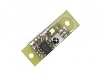
Low cost remote control IR receiver module is now completed (attached picture). Muting output for driving a muting relay and indicator LED are also provided. The module measures 18 x 46mm.
ISD player performance was significantly improved by using a balanced DEM injector for the TDA1541A.
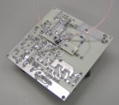
The balanced DEM clock injector offers extreme low jitter DEM clock (comparable with bit clock jitter). The signal is ac-coupled into pins 16 and 17 using 1nF capacitors. The balanced signal is generated using two high-speed NOR gates. The circuit has to be kept very compact in order to ensure maximum performance. I attached a photograph of this new (and final) DEM injector, mounted on a TDA1541A DAC module.
I also tested the DEM injector from Henk ten Pierick, but the signals look messy on the oscilloscope, and the sound quality was far from optimal. Problem with this circuit is poor signal quality, resulting in poor sound quality and reliability issues.
Various single-ended DEM clock injectors were also tested. Some performed very well, but had issues with reliability (thermal drift in the TDA1541A caused these circuits to fail).
Dividers that divide the masterclock down to say 352.8 KHz add significant jitter and interference and are not suitable for this application. I used the synchronously reclocked bit clock (1.4112 MHz) to drive the balanced DEM injector.
Based on experiments, the TDA1541A DEM clock makes or breaks TDA1541A sound quality. The Philips datasheet DEM clock application performed worst, poor bass, smeared sound and lack of micro detail. It functions reliably though.
Experiments also showed that ALL signals entering a DAC chip will affect sound quality, not only the timing signal (bit clock). For the TDA1541A chip this means that all I2S signals plus DEM clock need to have extreme low jitter and should inject as little HF / RF energy as possible into the chip. Inter-modulation between various clock sources should be avoided. This means that the DEM clock must at least run fully synchronous with the I2S signals, better is using exactly the same frequency as one of the I2S timing signals (WS or BCK).
I designed a small synchronous reclocker module for the TDA1543 and TDA1541A modules that plugs into the on-board I2S connector. The reclocker has 2 high-speed SMD flip-flops on board.
Low cost remote control IR receiver module is now completed (attached picture). Muting output for driving a muting relay and indicator LED are also provided. The module measures 18 x 46mm.
ISD player performance was significantly improved by using a balanced DEM injector for the TDA1541A.
The balanced DEM clock injector offers extreme low jitter DEM clock (comparable with bit clock jitter). The signal is ac-coupled into pins 16 and 17 using 1nF capacitors. The balanced signal is generated using two high-speed NOR gates. The circuit has to be kept very compact in order to ensure maximum performance. I attached a photograph of this new (and final) DEM injector, mounted on a TDA1541A DAC module.
I also tested the DEM injector from Henk ten Pierick, but the signals look messy on the oscilloscope, and the sound quality was far from optimal. Problem with this circuit is poor signal quality, resulting in poor sound quality and reliability issues.
Various single-ended DEM clock injectors were also tested. Some performed very well, but had issues with reliability (thermal drift in the TDA1541A caused these circuits to fail).
Dividers that divide the masterclock down to say 352.8 KHz add significant jitter and interference and are not suitable for this application. I used the synchronously reclocked bit clock (1.4112 MHz) to drive the balanced DEM injector.
Based on experiments, the TDA1541A DEM clock makes or breaks TDA1541A sound quality. The Philips datasheet DEM clock application performed worst, poor bass, smeared sound and lack of micro detail. It functions reliably though.
Experiments also showed that ALL signals entering a DAC chip will affect sound quality, not only the timing signal (bit clock). For the TDA1541A chip this means that all I2S signals plus DEM clock need to have extreme low jitter and should inject as little HF / RF energy as possible into the chip. Inter-modulation between various clock sources should be avoided. This means that the DEM clock must at least run fully synchronous with the I2S signals, better is using exactly the same frequency as one of the I2S timing signals (WS or BCK).
I designed a small synchronous reclocker module for the TDA1543 and TDA1541A modules that plugs into the on-board I2S connector. The reclocker has 2 high-speed SMD flip-flops on board.
Attachments
- Status
- Not open for further replies.
- Home
- Source & Line
- Digital Source
- Lossless SD-card player