here's how I implemented a soft start based on the CL60 and a timer circuit from Sylvain Bergeron.
The soft start has its own small transformer and power supply, the switch on the front panel activates the soft start:
a double relay is switched on that puts the mains on the 500VA transformer with a thermistor CL60 in series,
after two seconds that thermistor is bypassed with a second relay, so that the mains is directly connected to the 500VA.
Some remarks about the circuit:
- you can omit or change the resistor R8, I needed it to drop the voltage to the relays.
- You can put a led in series with R5 bleeder resistor as power on light.
- I used dip switches with R1-R4 so I can choose the delay of relay 2.
Regards,
Danny
Attachments
One more question about R15/R16 ...
I built the "Cvillar Board" version with cascode and double output,
only R115 and R116 is installed. With 2K2 an TH01/TH02 at 4K7 I
could it only get biased to 200mV. I changed R115/R116 to 7,5k
but now I think thermal regulation is not working. To turn Bias to
0,6V in this setup without a prob is possible.
So maybe 4K7 could be better choice ??? Any ideas ?
Michael
4k7 is probably better, but some people run the amp even without thermistors. The effect of your thermistors is relatively small now, so if you run into problems with keeping the dc offset down, then you might want to find some other thermistors.
I like this set up.here's how I implemented a soft start based on the CL60 and a timer circuit from Sylvain Bergeron.
What is Vgs of the 610 after the mpsa56 has fired to pull in the FET fast?
4k7 is probably better, but some people run the amp even without thermistors. The effect of your thermistors is relatively small now, so if you run into problems with keeping the dc offset down, then you might want to find some other thermistors.
Without was my test. Now with TH01/02 4K7 and resistors at 6K8 works fine.
Michael
Fairchild MOSFETs
I puchased a large quantity of Fairchild FQA12P20/FQA19N20C pairs in order to receive quantity pricing.
I have more than a few left.
I think $12.50 per pair shipped in the contiguous U.S. is a fair asking price.
I puchased a large quantity of Fairchild FQA12P20/FQA19N20C pairs in order to receive quantity pricing.
I have more than a few left.
I think $12.50 per pair shipped in the contiguous U.S. is a fair asking price.
Tech DIY Company Store
$4.00 a pair. Sorry.
Patrick
PS There are lots of people here who got hundreds during the group buys.
I am sure they are more than willing to part with them at USD12 per pair.
$4.00 a pair. Sorry.
Patrick
PS There are lots of people here who got hundreds during the group buys.
I am sure they are more than willing to part with them at USD12 per pair.
Last edited:
Someone asked me through PM about why I used different source and feedback resistor values for the 2SK170 and 2SJ74.
This has been explained multiple time in this forum, so please read through them first before you ask.
It is only applicable when you use 2SK1530/2SJ201 MOSFETs for the output stage, and that you want to do gain balancing for the positive and negative half.
You do not have to use these different values.
It still works with values from the original article.
Patrick
Last edited:
Tech DIY Company Store
$4.00 a pair. Sorry.
Patrick
PS There are lots of people here who got hundreds during the group buys.
I am sure they are more than willing to part with them at USD12 per pair.
Mine are geniune Fairchild parts and matched. Thanks for your input though.
Are you suggesting that those from jackinnj or from the Group Buys are not genuine Fairchild parts ?
Patrick
Patrick
Are you suggesting that those from jackinnj or from the Group Buys are not genuine Fairchild parts ?
Patrick
Do we need to waste time on such nonsense? Really?
I have better things to do and I'm sure you do as well.
I'm not implying anything, I'm simply stating what I have to offer.
It seems to me as though you're trying to stir up some kind of trouble of which I want no part.
If you're unhappy with my asking price then that's fine. I see no reason for any kind of back and forth.
Last edited:
i set the pots to a minimum and after double checking all my connections, I fired up the amp and after maybe 5 seconds it started to smoke next to R12 (on Cviller's latest board-.47R) so i quickly shut it off. I was measuring DC Volts on the speaker outputs when it happened, and i measured 5mV. What am I doing wrong?
I measured 17VDC from my rectifier boards.
I measured 17VDC from my rectifier boards.
How did you measure that your pots were at a minimum? Could you post some pics of your setup?
thanks for the quick reply, I turned them clockwise all the way and got .2 ohms on all of them
but after spot checking the P2 on that channel I'm getting 60 ohms with the pot turned to minimum? maybe i didn't measure it right before... or maybe there's a bad solder joint on one of the legs?
but after spot checking the P2 on that channel I'm getting 60 ohms with the pot turned to minimum? maybe i didn't measure it right before... or maybe there's a bad solder joint on one of the legs?
Last edited:
I think the problems are the active devices around the pots. Try doing the measurements both ways with your meter probes. My best guess is that you have them turned the all the way in the wrong direction...
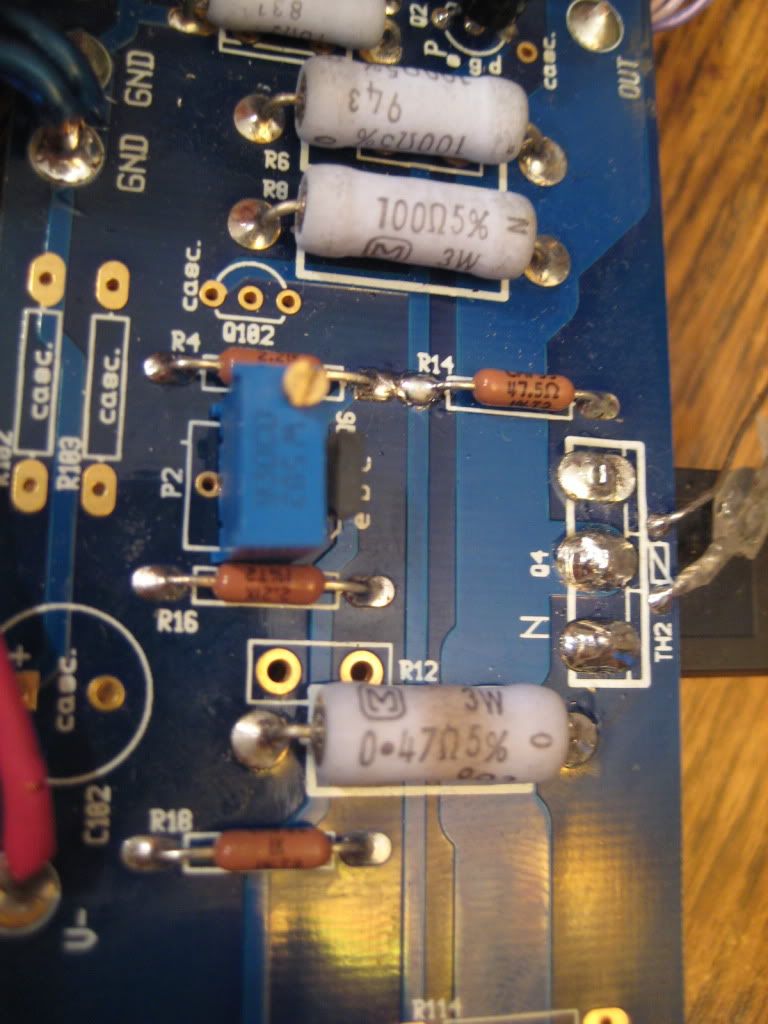
here is the affected area. ignore the red wire, as its the V- from V- confusing i know🙁
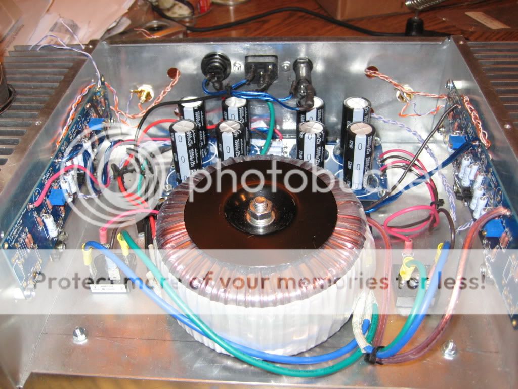
here is my setup if it helps any. Thanks
Last edited:
Damn Dusta,
Your boards look like mine!
It's easier than one would think to burn out parts, you are in good company.
Christian is more than likely right. Pots set the wrong direction. Easy to do.
Replace the bad parts and try again. Careful to NOT burn the board removing old parts.........it get's costly, don't ask.
Christian,
I'm still waiting on my parts from Jack.
Tests went well, I hope.
Ron
If you had a bulb serial connected to the mains, you wouldn't have burnt anything.
With some luck, nothing is burnt though, just a little toasted resistors.
With some luck, nothing is burnt though, just a little toasted resistors.
Last edited:
I sent out about 30 F5 kits last week --
I always test out my amps (I have 4 in the listening room) with a variable supply (PS5010) and pair of fused DVMs (Tektronix DM511). The supply will only do 400mA, but that's enough to get the bias and thermals stable. When the amp is stable at 400mA, I switch to my big testing supply -- it takes about an hour to get the combination of bias, thermal stability and offset correct, but a good investment in time. You can do much the same thing with a variac and a bipolar supply but FUSE the rails!
I always test out my amps (I have 4 in the listening room) with a variable supply (PS5010) and pair of fused DVMs (Tektronix DM511). The supply will only do 400mA, but that's enough to get the bias and thermals stable. When the amp is stable at 400mA, I switch to my big testing supply -- it takes about an hour to get the combination of bias, thermal stability and offset correct, but a good investment in time. You can do much the same thing with a variac and a bipolar supply but FUSE the rails!
I think the problems are the active devices around the pots. Try doing the measurements both ways with your meter probes. My best guess is that you have them turned the all the way in the wrong direction...
wouldn't I get a reading closer to 1.5K? (2.2k parallel w/ 5k) When I turned P2 the other way (ccw) resistance was increasing.
Do you remember what your minimum resistance was from the pots?
Bob + Jack-You're right, I think I did jump the gun and not setup proper precautions with the power supply. Once I get things checking out, I'll rig a bulb in series so nothing further damages
Last edited:
- Home
- Amplifiers
- Pass Labs
- F5 power amplifier